LED Wizard 8 Documentation


Intro to LED Wizard 8 Docs
Getting Started
System Requirements
Installation
Screen Layout
LED Wizard Basics
Basic Workflow
Operating Modes
Defaults and Preferences
New in Version 8
Data Clean Up Tool
Module Filtering
LED Wizard Fonts
LED Wizard 8 Database
Population Scaling Tool
Graphical Population Scaling
Auto Stats and Title Block Merging
Auto Power Supply Loading
Auto Dimensioning
Single Run Populations
Create Guide Paths from Open Vector Paths
Freehand Drawing Tool
Power Supply Colors
New Auto Power Supply Loading Options
Multiple Document Interface
Power Supply Rotation
Population Library
Core Series Flexible Mode
Creating LED Module Layouts
Using the PowerFlow Tool
Creating and Editing LED Modules
Scaling LED Graphics
Working with Guidepaths
Working with Selections
Editing Existing Selections
Cabinet Layouts
Parallel Layouts
Module Rotations
Reusing Module Layouts
Target Density
LED Property Bar
Using Power Supplies
Using Title Blocks
Multiple Module Title Blocks
Title Block Variables
Using Guidelines
Copy and Paste
Importing Files
From Adobe Illustrator
From Corel Draw
From AutoCAD
Exporting Files
Editing Text
Zooming
Vector Editing
Loop Editing
Tools, Tabs and Property Bars
PowerFlow
PowerFlow Tool
PowerFlow Property Bar
PowerFlow Tab
PowerFlow Tool Keyboard Shortcuts
Semi-Automatic Populations
Layout Tool
Data Clean Up Tool
Auto Mounting Holes Tool
Assign Letters Tool
Scale Tab
Summary Tab
PS Tab
Objects Tab
Layers Tab
History Tab
Job Tab
Text Edit Tool
Vector Edit Tool
Keys for Vector Editing
Loop Edit Tool
On Screen Digitizing Tool
Object Property Bar
Group Property Bar
Guideline Property Bar
Measure Tool Property Bar
Bitmap Property Bar
LED Object Property Bar
Job Color Property Bar
Menu Reference
File Menu
New
Open
Open Recent
Save
Save As
Save Copy As
Close
Snapshots Menu
Import
Scan
Export
Export Scaled PDF
Email PDF
Email
Print
Exit
Edit Menu
Undo
Redo
Cut
Copy
Paste
Paste Special
Paste in Place
Delete
Duplicate
Select All
Vector/Node Tools
Vector - Insert
Vector - To Line
Vector - To Arc
Vector - To Bezier
Vector - Break Loop
Vector - Set St/End Point
Vector - Join St/End Point
Vector - Move Opening
Vector - Add Vertical Guide
Vector - Add Horizontal Guide
Reorder Loops
Unexplode Vector Paths
Purge Undo/History
Document Properties
View Menu
Zoom commands
Toolbox menu
Custom Toolbars
Refresh
Show Fill Colors
Show Stroke Colors
Show Grid
Show Guidelines
Show Rulers
Show Loop Direction
Show Job Color Palette
Show Side Bar
Show Info Bar
Show Help Bar
Show Group Member Names
Highlight Small Vectors
Transparent Background
Reset Toolbar Layout
Layout Menu
Layers
Guides commands
Shapes commands
Rounded Rectangle
Polygon
Arrow
Layout Properties
Size to Fit
Show Layout Size
Snap to Grid
Snap to Guidelines
Snap Dimensions to Graphics
Selectable Guidelines
Auto Square
Create Auto Dimensions
Arrange Menu
Align Tools
Distribute Tools
Group Tools
Locked
Editable
Select Only by Edge Click
Allow Options
Break Into Loops
Break Into Outer Loops
Combine
Close All Loops
Remove All Inner Loops
Horizontal Mirror
Vertical Mirror
Z Order Tools
Move to Layer
To Top
To Bottom
Move One Up
Move One Down
Text Menu
Text Tool
Break Apart
Live Spell Checking
Convert to Text
Change Copy
Change Case Tools
Font Wizard
Font Layout
Vertical
Add Variable Text
Edit Variable Text
Remove Variable Text
Image Menu
Vectorize
Crop Tool
Rasterize
Rotate +/- 90 Degrees
Flip Horizontal/Vertical
Invert
Commit Rotation
1:1 Zoom
Save (Image) As
Cut at Max Length
Reorder Tubes
Power Supply Template Setup
Multi Excel Update
LED Menu
PowerFlow LED Tool
Assign Letters
Statistics Menu
Update Statistics
Update Grouped Statistics
Recreate Statistics
Respace Stats
Uniformly Respace Stats
Merge Title Block Template
Remove Title Block
This Document is a Title Block
Optimized Title Block Text
Create Module Hole Layer
Create Router Layer
Auto Mounting Holes Tool
Update Vector Guidepaths
Remove Vector Guidepaths
Create Guide Paths from Open Vector Paths
Recreate with Bezier Curves
Rasterize-Vectorize Filter
Remove LED Modules
Populate Menu
Populate
Populate All
Repopulate
Populate Along Guide
Populate Stroke Inline
Populate Single Horizontal Serif
Paste Selected Runs
Insert Parallel Guide Line
Add to Population Library
Respace Selected Runs
Auto Respace
Auto Join
Filtering Enabled
Calculate Stroke Width at Cursor
Modify Menu
Select All Modules in Run
Select All Modules in Letter
Select Stroke
Add Run to Selection
Rotate Menu
Reset Primary Rotation Angle
Reset Secondary Rotation Angle
Alternate Rotations
Rotate 90 degrees
Rotate 45 degrees
Rotate 45 degrees - Alternating
Rotate Counter-Clockwise (Left)
Rotate Clockwise (Right)
Flip Primary Rotation Angle
Flip Secondary Rotation Angle
Convert to Perpendicular Alternate Rotated
Density Menu
Increase Density
Increase Density For Entire Run
Decrease Density
Decrease Density For Entire Run
Uniform Spacing
Uniform Spacing For Entire Run
Add / Remove Density Segment
Show Density Segments
Clear All Density Segments
Append Module
Insert Single Module
Mirror Horizontal
Mirror Vertical
Fill To Cursor
Break Run
Move Opening
Convert To Line
Shift Menu
Shift Inward
Shift Outward
Slide Backward
Slide Forward
Slide to Max Spacing
Reconnect Runs
Center in Stroke
Center in Stroke w/Cleaning
Mouse Menu
Nudge
Nudge Faster
Delete Current Run
Delete Module(s)
Delete Module(s) and Break
Delete All Modules in Current Letter
Delete Modules in All Letters
Remove Overlapping Modules
PowerFlow Measure Mode
Ensure Reachability
Change All Modules
PS Menu
Power Supply Edit Mode
Add Selection Rectangle Modules to Power Supply
Connect Run to Power Supply
Remove Run from Power Supply
Add New Power Supply
Remove Power Supply
Add One Power Supply per Letter
Add One Power Supply per Letter (Auto Select PS)
Add One Power Supply for All Letters
Add One Power Supply for All Letters (Auto Select PS)
Add Optimal Power Supplies by Letter
Add Optimal Power Supplies by Run
Add Optimal Power Supplies by Modules (breaks runs)
Connect Current Letter to Power Supply
Remove Current Letter from Power Supply
Drawing Left
Drawing Above
Drawing Right
Drawing Below
Next Drawing Position
Hide Power Supplies
Arrange Power Supplies in a Grid
Options Menu
Show Connecting Wires
Show Run Numbers
Show Power Supply Wires
Show Power Supply Data Boxes
Show Power Supply Data Box Borders
Show Module Drawings
Show Letters and Stats
Show Vector Guidepaths
Show Stroke Width Line
Enable Dynamic Repop
Power Supply Color Mode
Auto Extend
Remove All Stray Modules
Refresh Run Numbers
PowerFlow Menu
Ctrl Enables Snapping
Non-Snapping Movement Auto Rotates
Non-Snapping Drag Auto Rotates
Show Stroke Circle
Excel Menu
LED Excel Link Setup
Update Excel
Reconnect
Auto Update Excel
Excel Enabled
Title Block Setup
Letter Statistics Setup
Legacy Statistics Template Setup
Power Supply Template Setup
Power Supply Pricing Setup
Module Pricing Setup
Filter Modules
Edit Face Materials
Legacy Letter Statistics Mode
Open Merged Titleblock File
Upload Log Files
Tools Menu
Options
General Tab
View Tab
Edit Tab
Save Tab
Text Tab
LED Tab
Tools Tab
Directories
Keyboard
High Color Toolbox
Switches
Update LED Database
Reload LED Database
Outline
Weld
Layout Tool
Vector Edit Tool
Loop Edit Tool
On Screen Digitize Tool
Freehand Drawing Tool
Data Prep Tool
Dimensions
Measure
Calculate Area
Channel Letter Return
Radius Corners
Convert Menu
Convert Beziers to Arcs
Convert Arcs to Beziers
Convert to All Lines
Convert Lines to Arcs
Convert Flat Blend to Simple Fills
Convert All Clippings Paths to Normal Paths
Convert All Clipping Paths to Normal Filled Paths
Detect Letters
Remove Coincident Loops Across Layout
Remove All Clipping Paths
Optimize Vectors
Find Self-Intersecting Loops
Force Loop Direction
Remove Duplicate Loops
Display Path Length
Reset Windows Explorer File Association
Open AppData Folder
Window Menu
Cascade
Tile Vertical
Tile Horizontal
[Documents]
Help Menu
Get Help
Login
Check for Web Updates
About LED Wizard
Misc
DXF Options
PDF Options
Shortcut Key Reference
Working with App Data Files
Previous  Next

4.5 Population Scaling Tool

LED Wizard 8 includes two easy methods for Scaling a populated object to a new size. The first is the Population Scaling Tool, which we talk about here. The second is Graphical Population Scaling. Both approaches let you start with a single population and scale it up and/or down to new sizes using the same module and depth.

Since many jobs require layouts to be created at multiple sizes from the same original artwork, this is a big time saver. In previous versions, this meant starting over with each size, since LED layouts don't scale like neon layouts.

The Population Scaling Tool should be used when you need to create multiple specific sizes from an original. For example, you have an original layout that is 24" tall channel letters, and you want to make versions at 20", 22", 26", 28", 30", and 32" sizes. The Graphical Population Scaling method is more suited to "fine tuning" a layout, or maybe making one or two copies at similar sizes. Maybe you made the layout at 24" but you realized that it was supposed to be at 26".

In either case, start with the initial layout and fine tune it in PowerFlow as the "master" layout for the other sizes. The module and depth will be inherited from this master and used across all of the new sizes.

For the Population Scaling Tool, there is a new Scale Tab to the right of the Powerflow tab at the top right of the screen. You may have to use the arrow keys at the top of the tabs to scroll over (you can adjust the width of the tabs by positioning the mouse over the vertical left edge of the tab, and clicking and dragging when you see the arrow cursor).

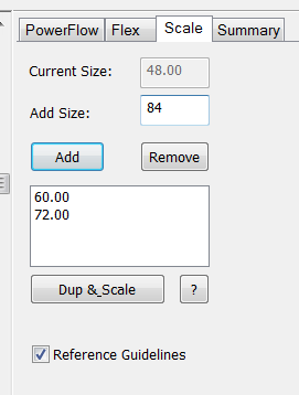
With the "master" layout selected with the Layout Tool, click on the Scale tab, which will bring up the interface for creating the new sizes. The first field is called **Current Size**, which is based on the height of bounding box of the selected object. In some cases, this will be correct, but in other cases you may need to adjust this value (see below).

If this value is correct, then you can use the Add Size field to add all the new sizes that you want to create. Just enter the size in inches or mm, and then click on the Add button. All the sizes you have entered will show up in the list below the Add and Remove buttons. To remove a size, just select it in the list and click on the Remove button.

When you have added all the new sizes you want, click on the Dup & Scale button, and the new sizes will be created in the current file. This option should be used when the new size is part of the same job, perhaps one main sign on the front of the building, and two smaller versions on the sides.

If your new sizes are intended to be their own layouts, then just copy and paste each size into a new layout. With Multiple Document Interface, you can have several windows open at the same time. You can consider having one layout with all the sizes, but not loaded with power supplies or having a title block template. Then you can copy each size into a new file and then finalize with power supplies and the title block. It is not necessary that the master file be saved prior to making scaled copies, but it is a good idea.

If the value of Current Size is not correct for your object, perhaps due to a rounded capital letter or a descender, then we can use the Reference Guidelines to measure the exact height that you want to use.

Click on the Reference Guidelines check box to display the guidelines used to determine the height. Adjust them as necessary, noting that the Current Size box will reflect the current value.

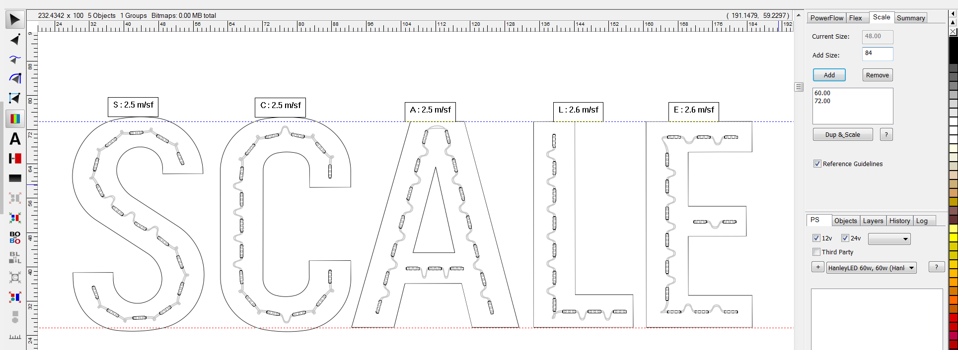
In this classic example, the text starts off with an "S" that goes above and below the "Square Cap Height" of these letters, which is 48". The actual height of the "S" is 50 1/4", but that's not the height we want to use when scaling. We want to use 48", so we adjust the guidelines to match the "A" instead of the "S".

Just to be clear, if we used the height value of 50 1/4" and scaled the text to 60", then the "S" would be 60" and the "A" would be 57 3/8", which is not what we want.

The same logic and procedure would be used if you had text of "Try." You would set the bottom Reference Guideline to the bottom of the "T", not the bottom of the "y".

Note: if you prefer to Scale your layout more visually, then use the Graphical Population Scaling method.


In this example, the original letter size was 24", and we made versions of 20", 18", 16", and 14" in the same layout.

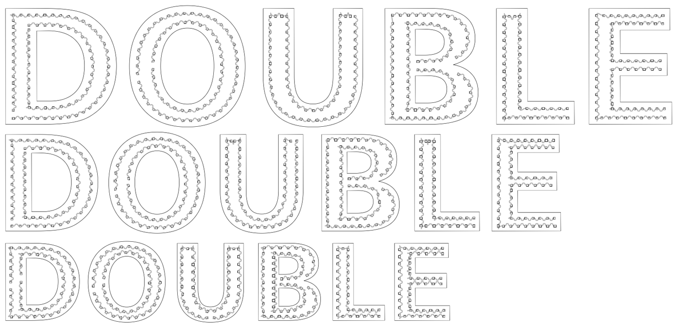
If your original layout is two runs of LEDs, and you have the runs positioned so that the Clearance = 1/2 the Run Gap, then this can be cleanly scaled up and down to new sizes. Note that with multiple runs, your Clearance and Run Gap will change with the new sizes, but the relationship between the Clearance and Run Gap will stay consistent.


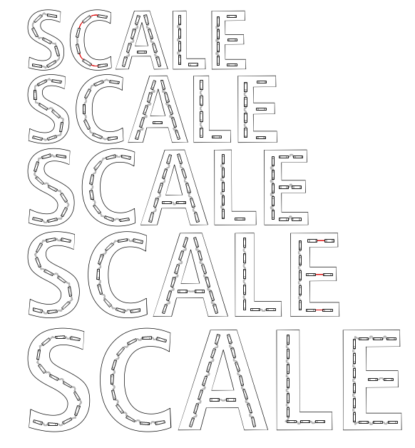
In this example, the original lettering was 48", and the scaled versions are 60" and 72"

If your size range is such that the complete set of layouts will need different numbers of runs of LEDs, then you will need to make multiple "masters" for each. For example, the single run master may be used for the layouts where the text height is 12-18", and the double run master may be used for the layouts from 18-30". The Population Scale feature does not start with a single run master and make a double run version, and you must pay attention to the stroke width coverage of the module for the selected depth at the new sizes.


Previous  Next
Was this helpful?          

Copyright (C) 2019-2023 Principal Lighting Group, LLC