|
|
Previous Next
8.1 File MenuThe File menu contains commands for managing your documents. New - Ctrl+NThis command creates a new document. We now support Multiple Document Interface, so you can open multiple documents. The document opens maximized by default. Open - Ctrl+OThe Open dialog allows you to load an existing .LW8 or .LW file for further modification, printing or export. The various fields are described below: Look inSelect the drive or directory you would like to open the file from. File NameEnter the name of the file you want to load, if you know the name, or choose one from the list of files below. Files Of TypeUse this drop down list box to choose which file type you would like to have listed for you to choose from. Use Snapshots (only when opening layouts)Check this to use the snapshot feature when saving and opening layouts. Thumbnail View as DefaultCheck this if you want the Open dialog to always open in thumbnail view. DateDate of last modified of the layout. SizeSize of the file in bytes. LayoutsUse this to instantly switch to the defined Layouts path. BackupsUse this to instantly switch to the Backups Folder. Note: Merge is now replaced by Import, and Delete is integrated with the dialog box. That is, you can simply press the Del key to delete a file. Open RecentThis submenu lists the 10 most recent files that you can open by clicking on the name. You can set the number of files to remember in the Tools | Options | Save tab. Save - Ctrl+SThe Save command will allow you to save the current layout to disk. If the layout you are working on already has been saved, selecting the Save command will automatically overwrite the existing layout. If you have not previously saved the layout, the Save As dialog box will be displayed and allow you to enter the filename as well as a description for that sign. You should always Save a layout in our native .LW8 file format in addition to exporting, in case you want to edit the original file. Save As - Ctrl+Shift+SThe Save As window allows you to save your file under a new name. Save inSelect the drive or directory you would like to save the file to. File NameEnter the name of your file here. You can type in a new directory--if you know it's name--and then press Enter to switch to it, and see the files in it. Save as TypeUse this drop down list box to choose the file type you wish to save your file as. The default is LED Wizard 8 (.lw8). There are older formats in order to use this layout with older versions of the software. Save Copy AsUse this variation on the Save As command to save a copy of your layout to a different file, without changing the name as it's known by the program. The Save As command also renames the current layout when you invoke that command, but Save Copy As does not. Close - Ctrl+WSelect this to close the current document. If there any unsaved changes, you will be asked if you want to save them first. This only closes the current document. The last used document will become the active document. Snapshots MenuSnapshots are a way to save works in progress, with automatic numbering. The snapshots are regular .lw8 files that are saved in the Snapshots folder under the defaults Layouts folder. The default location will be Documents\LED Wizard 8\Layouts\Snapshots. Open SnapshotOpen a previously created snapshot. Save New Numbered SnapshotThis command will save a new .lw8 file as a numbered snapshot file. You just have to press Ctrl+Alt+S to save a new version of the current document. You don't have to pick a unique filename in order to have a point-in-time snapshot of the document. Import - Ctrl+F8The Import command is used to bring in files from other software, such as AutoCAD, Adobe Illustrator, Corel DRAW, etc. 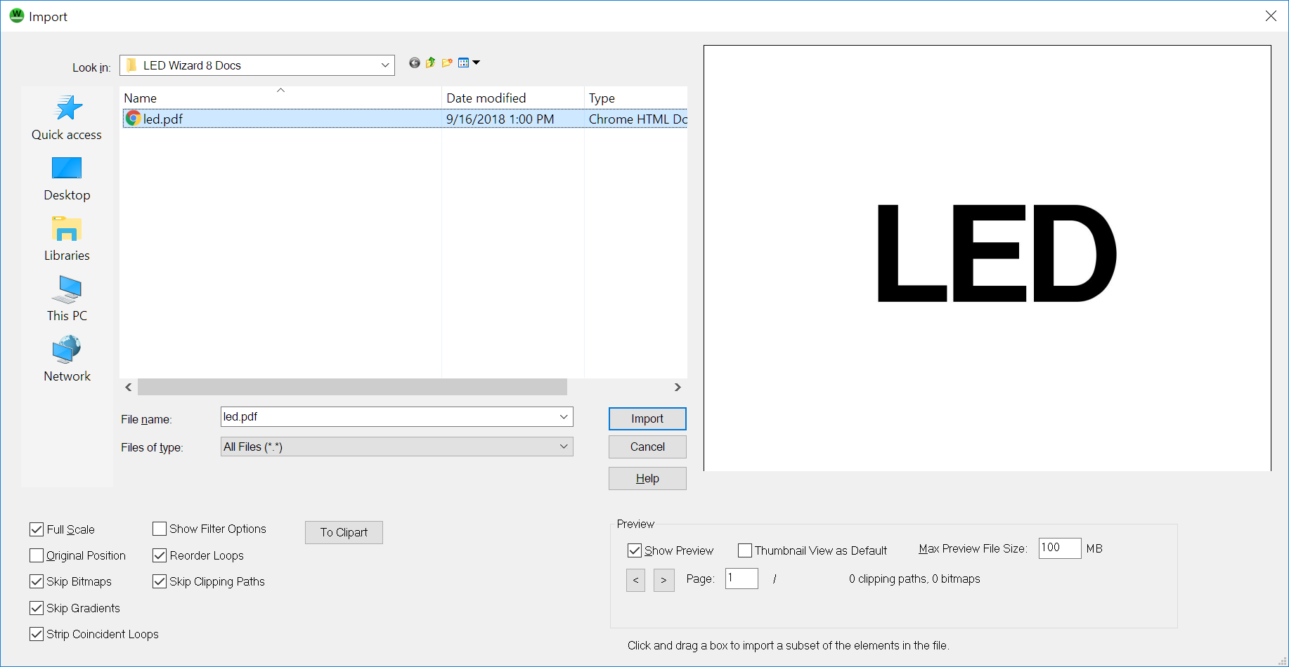
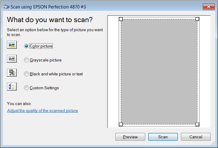
Below is a description of this dialog box: Look InSelect the folder from this list. File nameEnter the name of the file you want to load, if you know the name. Files of TypeChoose the type of file you want to open. Popular formats include PDF, AI, EPS, and DXF. The PDF format now has two options: PDF (PDFTron), which is the default, and Interpreted Postscript/PDF (Legacy). The default PDF (PDFTron) will generally provide better results and should be used first. Full ScaleClick this to bring in the graphic at full scale. When this is NOT checked, you will be required to scale the object, so if you need to keep the original size, check this box before clicking on Import. Show PreviewClick on this to view a preview of the selected graphic file in the large box at the very right side of the dialog box. Thumbnail View as DefaultCheck this if you want the Import dialog to always open in thumbnail view. Original PositionCheck this if you want import the file using the original position it was create with it. With this option, if you export an object, and then import again, it automatically appear in the same position as the original file. This option, therefore, eliminates the positioning mode that normally occurs after this dialog box terminates. Show Filter OptionsCheck this box to display the options dialog for the filter used, or uncheck it to skip the dialog entire. Maximum Preview File SizeSpecify the maximum size of the files that LED Wizard should try to preview. Set this to an appropriate number of bytes so that you don't wind up waiting for huge files to be loaded for previewing. Skip BitmapsThis option will skip all bitmap images, which should be checked unless the data you need is a bitmap. You can compare the preview with what you end up importing to tell if the relevant data is a bitmap image and must be imported along with the vector graphics. Skip Clipping PathsUsing this option can streamline importing complex designs created in software like Adobe Illustrator, in which clipping paths (or clipping masks) are used liberally, and can cause problems with finding only the data you need to create an LED layout. Skip GradientsUse this option to ignore gradient fills when importing, which are rarely helpful. Import CropYou can draw a crop box in the preview window to Import only certain parts of a large design file. This will only work with vector files, and not bitmap files. Please see the section on the Data Clean Up Tool for more details on the file importing and data clean up processes. ScanScanThis command will allow you to bring in a scanned image for any camera or scanner supported by the Windows Image Acquisition (WIA) architecture. WIA is similar to TWAIN, but is more integrated with Windows and has more advanced features.
The standard user interface for the device will appear, and it will take over the scanning process. Once the scanning is done, a dotted red box will appear in the window, letting you place the image in the layout. Export - Alt+XThe Export command lets you create a new file from your layout in many file formats, including EPS, AI, PDF, DXF and various bitmap formats. 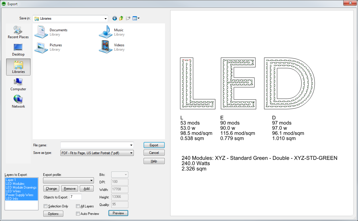
Select the format to use and then, if you want to specify options, click the Options button. Some of the special options in LED Wizard are described below: Layers to ExportClick these layers to toggle them on or off when exporting. The special LED layers are: LED Modules. These are the actual modules, not including the drawings. If "LED Module Drawings" is not checked, a simple rectangle will be exported for each module. LED Module Drawings. Selecting this causes the module drawings to exported as well. LED Wires. This option exports the wires connecting each module. This is not always necessary for estimates. Power Supply Wires. Select this to export the wires connecting the modules to the power supplies. LED Info. Select this to export the statistics (letter and summary). Module Markings. This is the data from the Router Layer indicating the position of each LED. Holes. These are the Mounting Holes from the Auto Mounting Holes Tool. Title Block. Select this layer to include the title block template. Letter Stats. This layer contains the letter stats in the upper right of the layout. Above the Letter Stats. This contains the stats above the letters, as selected in the Options dialog box, LED tab. Export ProfileThis is a saved export profile you can select from, which just includes Layers to Export. ChangePress this to update the selected preset with the currently selected Layers to Export. RemovePress this to remove the selected preset. AddPress this to add a new preset. Objects to ExportThis is a simple count of the objects what will be exported, based on Selected Only and Layers to Export. Selection OnlyThis determines whether the entire layout is exported, or just the current selection. All LayersPress this to select all layers for exporting. BitsWhen exporting to a bitmap format, this selects the bits per pixel. You must use 32 and a compatible bitmap format, such as TIFF or PNG, to include an alpha channel and achieve transparency. DPIThis can be used to select a specific Dots Per Inch. WidthThis is the total number of pixels wide the exported bitmap will be. HeightThis is the total number of pixels high the exported bitmap will be. QualitySelect the compression quality, when using JPEG format. OptionsPress this to view or change additional options for the selected format. Auto PreviewCheck this box to enable automatic preview mode. PreviewPress this button to generate a preview of the export, showing which of the selected layers will be exported. Export Scaled PDFThis special export mode exports your LED layout to a PDF file at a US letter, US Tabloid, or international A4 or A3 page size, scaling everything down to fit the page. See [[Export]] for information on the Export dialog box. Email PDFThis command will immediately create a PDF file and launch your email software using the MAPI system.
This creates an email with the current layout as an attachment.
This creates a JPEG bitmap image of the current layout and attaches it to a new email, ready to send.
This creates an EPS file of the current layout and attaches it to a new email, ready to send.
This sends an Adobe Illustrator file of the current layout and attaches it to a new email, ready to send. The version used is 6, which supports the major features, including images. Note: Images in EPS or AI files are not compressed, and it's not a good idea to email such files if the images are large. In this case, we recommend exporting the file and then zipping it before emailing. Please note: this feature uses your default Windows email program, such as Microsoft Outlook, and creates a new email with the file as an attachment. It will not create an email using a web-based email system such as Gmail. To send a file with web-based email, Save or Export the file, create the email, and add the file as an attachment. Print - Ctrl+PThis selection will allow you print the current layout. You can print the layout actual size, fit it to the page, or print it at a particular scale. There are also options for printing colors, printing just the selected object (if any), automatically centering the layout on the page, and printing each color in the layout on separate pages as black color separations. Finally, you can specify how many copies you would like. Here is a description of the Print dialog box: PrinterSelect the printer you want to use from this drop down listbox. This list shows the printer and port it?s currently connected to. Print ColorsCheck this box when you want to print all the colors in the layout. Print SelectionCheck this option if you want to print only the selected object. This option will be unavailable if there is no object currently selected. You can print either a single object or an entire group using this option. Zoom to SelectionThis checkbox will cause the printed region of the layout to be zoomed to the current selection, and it will print as expected, whether or not the selection is inside the layout boundaries. Print Layout FrameCheck this if you want to the layout?s border to print as a thin box around the layout. This is useful in showing the substrate?s size. Center on PageCheck this box to force the layout to be centered on the page as you change the size using the Layout Size options described below. Print as Black SeparationsUse this option to print several different colors in your design on separate pages, one page per color. When this is checked, all uncolored objects will be printed on every page, so that they may act as registration marks. All colored objects will be printed on separate pages, but always in black, regardless of the original color. PreviewThis box shows a preview of the layout as it will be printed on the page. You can drag the dark gray area (which represents the layout) and move it around to better position it. Layout Size - Actual SizeSelect this checkbox when you want the printout to be the same actual size as your layout (for example, one inch in your layout will be one inch on the paper). Layout Size - Fit To PageSelect this option to have the layout be sized to fit in the page. This will preserve the aspect ratio of the layout, so that, usually, there will be space on the top and bottom or left and right sides. Layout Size - ScaleSelect this checkbox when you want to specify a particular scaling value for the layout. The numeric value to the right of the checkbox is a percentage of the actual or original size of the layout. For example, a 200% scale with will make the layout appear twice as large on the page compared to its original size. You must move to another dialog item to see the change take place. Layout Size - WidthYou can specify a particular width for the layout by entering a number into this box. The Height box below it will change accordingly so that the overall aspect ratio of the layout is not changed. You must move to another dialog item to see the change take place. Layout Size - HeightYou can specify a particular height for the layout by entering a number into this box. The Width box above it will change accordingly so that the overall aspect ratio of the layout is not changed. You must move to another dialog item to see the change take place. SetupPress this button to configure the printer currently shown in the Printers list. You can change the orientation between landscape and portrait, in addition to setting other options, which are specific to your printer. ExitThis select command to exit the software. For any unsaved documents, you will be asked if you want to save them. You can respond with Yes, No, or Cancel. For any document in which you press Cancel, exiting of the software will be canceled. If you elect to save a document, but press Cancel, exiting will be canceled. Previous Next |