Removes all LED modules that fall outside of any letter or object.
This is a rare situation, and sometimes you can't see any "stray" modules, but a couple of ways you can tell if you have them:
- Your stats show more modules than what you're seeing in the layout.
- Your layout size is very large relative to your actual design.
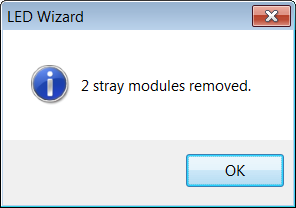
When you run this function, a dialog box will confirm as follows:
 LED Wizard 8 Documentation