LED Wizard 8 Documentation


Intro to LED Wizard 8 Docs
Getting Started
System Requirements
Installation
Screen Layout
LED Wizard Basics
Basic Workflow
Operating Modes
Defaults and Preferences
New in Version 8
Data Clean Up Tool
Module Filtering
LED Wizard Fonts
LED Wizard 8 Database
Population Scaling Tool
Graphical Population Scaling
Auto Stats and Title Block Merging
Auto Power Supply Loading
Auto Dimensioning
Single Run Populations
Create Guide Paths from Open Vector Paths
Freehand Drawing Tool
Power Supply Colors
New Auto Power Supply Loading Options
Multiple Document Interface
Power Supply Rotation
Population Library
Core Series Flexible Mode
Creating LED Module Layouts
Using the PowerFlow Tool
Creating and Editing LED Modules
Scaling LED Graphics
Working with Guidepaths
Working with Selections
Editing Existing Selections
Cabinet Layouts
Parallel Layouts
Module Rotations
Reusing Module Layouts
Target Density
LED Property Bar
Using Power Supplies
Using Title Blocks
Multiple Module Title Blocks
Title Block Variables
Using Guidelines
Copy and Paste
Importing Files
From Adobe Illustrator
From Corel Draw
From AutoCAD
Exporting Files
Editing Text
Zooming
Vector Editing
Loop Editing
Tools, Tabs and Property Bars
PowerFlow
PowerFlow Tool
PowerFlow Property Bar
PowerFlow Tab
PowerFlow Tool Keyboard Shortcuts
Semi-Automatic Populations
Layout Tool
Data Clean Up Tool
Auto Mounting Holes Tool
Assign Letters Tool
Scale Tab
Summary Tab
PS Tab
Objects Tab
Layers Tab
History Tab
Job Tab
Text Edit Tool
Vector Edit Tool
Keys for Vector Editing
Loop Edit Tool
On Screen Digitizing Tool
Object Property Bar
Group Property Bar
Guideline Property Bar
Measure Tool Property Bar
Bitmap Property Bar
LED Object Property Bar
Job Color Property Bar
Menu Reference
File Menu
New
Open
Open Recent
Save
Save As
Save Copy As
Close
Snapshots Menu
Import
Scan
Export
Export Scaled PDF
Email PDF
Email
Print
Exit
Edit Menu
Undo
Redo
Cut
Copy
Paste
Paste Special
Paste in Place
Delete
Duplicate
Select All
Vector/Node Tools
Vector - Insert
Vector - To Line
Vector - To Arc
Vector - To Bezier
Vector - Break Loop
Vector - Set St/End Point
Vector - Join St/End Point
Vector - Move Opening
Vector - Add Vertical Guide
Vector - Add Horizontal Guide
Reorder Loops
Unexplode Vector Paths
Purge Undo/History
Document Properties
View Menu
Zoom commands
Toolbox menu
Custom Toolbars
Refresh
Show Fill Colors
Show Stroke Colors
Show Grid
Show Guidelines
Show Rulers
Show Loop Direction
Show Job Color Palette
Show Side Bar
Show Info Bar
Show Help Bar
Show Group Member Names
Highlight Small Vectors
Transparent Background
Reset Toolbar Layout
Layout Menu
Layers
Guides commands
Shapes commands
Rounded Rectangle
Polygon
Arrow
Layout Properties
Size to Fit
Show Layout Size
Snap to Grid
Snap to Guidelines
Snap Dimensions to Graphics
Selectable Guidelines
Auto Square
Create Auto Dimensions
Arrange Menu
Align Tools
Distribute Tools
Group Tools
Locked
Editable
Select Only by Edge Click
Allow Options
Break Into Loops
Break Into Outer Loops
Combine
Close All Loops
Remove All Inner Loops
Horizontal Mirror
Vertical Mirror
Z Order Tools
Move to Layer
To Top
To Bottom
Move One Up
Move One Down
Text Menu
Text Tool
Break Apart
Live Spell Checking
Convert to Text
Change Copy
Change Case Tools
Font Wizard
Font Layout
Vertical
Add Variable Text
Edit Variable Text
Remove Variable Text
Image Menu
Vectorize
Crop Tool
Rasterize
Rotate +/- 90 Degrees
Flip Horizontal/Vertical
Invert
Commit Rotation
1:1 Zoom
Save (Image) As
Cut at Max Length
Reorder Tubes
Power Supply Template Setup
Multi Excel Update
LED Menu
PowerFlow LED Tool
Assign Letters
Statistics Menu
Update Statistics
Update Grouped Statistics
Recreate Statistics
Respace Stats
Uniformly Respace Stats
Merge Title Block Template
Remove Title Block
This Document is a Title Block
Optimized Title Block Text
Create Module Hole Layer
Create Router Layer
Auto Mounting Holes Tool
Update Vector Guidepaths
Remove Vector Guidepaths
Create Guide Paths from Open Vector Paths
Recreate with Bezier Curves
Rasterize-Vectorize Filter
Remove LED Modules
Populate Menu
Populate
Populate All
Repopulate
Populate Along Guide
Populate Stroke Inline
Populate Single Horizontal Serif
Paste Selected Runs
Insert Parallel Guide Line
Add to Population Library
Respace Selected Runs
Auto Respace
Auto Join
Filtering Enabled
Calculate Stroke Width at Cursor
Modify Menu
Select All Modules in Run
Select All Modules in Letter
Select Stroke
Add Run to Selection
Rotate Menu
Reset Primary Rotation Angle
Reset Secondary Rotation Angle
Alternate Rotations
Rotate 90 degrees
Rotate 45 degrees
Rotate 45 degrees - Alternating
Rotate Counter-Clockwise (Left)
Rotate Clockwise (Right)
Flip Primary Rotation Angle
Flip Secondary Rotation Angle
Convert to Perpendicular Alternate Rotated
Density Menu
Increase Density
Increase Density For Entire Run
Decrease Density
Decrease Density For Entire Run
Uniform Spacing
Uniform Spacing For Entire Run
Add / Remove Density Segment
Show Density Segments
Clear All Density Segments
Append Module
Insert Single Module
Mirror Horizontal
Mirror Vertical
Fill To Cursor
Break Run
Move Opening
Convert To Line
Shift Menu
Shift Inward
Shift Outward
Slide Backward
Slide Forward
Slide to Max Spacing
Reconnect Runs
Center in Stroke
Center in Stroke w/Cleaning
Mouse Menu
Nudge
Nudge Faster
Delete Current Run
Delete Module(s)
Delete Module(s) and Break
Delete All Modules in Current Letter
Delete Modules in All Letters
Remove Overlapping Modules
PowerFlow Measure Mode
Ensure Reachability
Change All Modules
PS Menu
Power Supply Edit Mode
Add Selection Rectangle Modules to Power Supply
Connect Run to Power Supply
Remove Run from Power Supply
Add New Power Supply
Remove Power Supply
Add One Power Supply per Letter
Add One Power Supply per Letter (Auto Select PS)
Add One Power Supply for All Letters
Add One Power Supply for All Letters (Auto Select PS)
Add Optimal Power Supplies by Letter
Add Optimal Power Supplies by Run
Add Optimal Power Supplies by Modules (breaks runs)
Connect Current Letter to Power Supply
Remove Current Letter from Power Supply
Drawing Left
Drawing Above
Drawing Right
Drawing Below
Next Drawing Position
Hide Power Supplies
Arrange Power Supplies in a Grid
Options Menu
Show Connecting Wires
Show Run Numbers
Show Power Supply Wires
Show Power Supply Data Boxes
Show Power Supply Data Box Borders
Show Module Drawings
Show Letters and Stats
Show Vector Guidepaths
Show Stroke Width Line
Enable Dynamic Repop
Power Supply Color Mode
Auto Extend
Remove All Stray Modules
Refresh Run Numbers
PowerFlow Menu
Ctrl Enables Snapping
Non-Snapping Movement Auto Rotates
Non-Snapping Drag Auto Rotates
Show Stroke Circle
Excel Menu
LED Excel Link Setup
Update Excel
Reconnect
Auto Update Excel
Excel Enabled
Title Block Setup
Letter Statistics Setup
Legacy Statistics Template Setup
Power Supply Template Setup
Power Supply Pricing Setup
Module Pricing Setup
Filter Modules
Edit Face Materials
Legacy Letter Statistics Mode
Open Merged Titleblock File
Upload Log Files
Tools Menu
Options
General Tab
View Tab
Edit Tab
Save Tab
Text Tab
LED Tab
Tools Tab
Directories
Keyboard
High Color Toolbox
Switches
Update LED Database
Reload LED Database
Outline
Weld
Layout Tool
Vector Edit Tool
Loop Edit Tool
On Screen Digitize Tool
Freehand Drawing Tool
Data Prep Tool
Dimensions
Measure
Calculate Area
Channel Letter Return
Radius Corners
Convert Menu
Convert Beziers to Arcs
Convert Arcs to Beziers
Convert to All Lines
Convert Lines to Arcs
Convert Flat Blend to Simple Fills
Convert All Clippings Paths to Normal Paths
Convert All Clipping Paths to Normal Filled Paths
Detect Letters
Remove Coincident Loops Across Layout
Remove All Clipping Paths
Optimize Vectors
Find Self-Intersecting Loops
Force Loop Direction
Remove Duplicate Loops
Display Path Length
Reset Windows Explorer File Association
Open AppData Folder
Window Menu
Cascade
Tile Vertical
Tile Horizontal
[Documents]
Help Menu
Get Help
Login
Check for Web Updates
About LED Wizard
Misc
DXF Options
PDF Options
Shortcut Key Reference
Working with App Data Files
Previous  Next

8.11.11 Auto Mounting Holes Tool
Production Module Only

A critical step in the process of designing and producing channel letters is defining where the holes are positioned on the letter backs and/or the sign cabinet. These holes could be for mounting the sign and/or for the module and power supply wiring.

The Auto Mounting Holes Tool makes it a snap to create mounting holes for an entire job in just a few minutes. The basis for this tool is that you can define the vertical and horizontal positions of these holes automatically, based on a few input parameters.

The tool works by letting you preview a layout of holes, make various adjustments, and then, when the layout is correct, press "Add Holes" to actually create the holes.

Here is the property bar and a description of the options.

Size

This is the size of the hole to use. To make a new Size, enter the value here as a decimal, and then also give it a Name in the next field, and then click on the green "+" symbol to add it.

Name

This is the name of the hole to use. The Name can be the same or different from the Size entered in the previous field.

Inline

This is the amount to inline, or offset, from the return for automatic positioning of the holes.

Max HS

This setting defines the maximum spacing between holes when using the Distributed mode. For example, you may have a cabinet where you want to enter a mounting hole every 12 inches.

(predefined holes)

The first drop down list shows the predefined mounting holes that you can select from. These are created from entering new Size and Name values and then saving them.

(number of rows)

The second drop down list lets you select the number of rows of holes to create, based on the horizontal guidelines. You can easily reposition these holes by dragging the guideline up or down.

(holes layer)

The third drop down list lets you select the name of the Layer for the holes, or create a new layer.

(crosshairs layer)

The fourth drop down list lets you select the name of the Layer for the crosshairs, or create a new layer.

Left Aligned

Press this to add holes to the left edge of the stroke.

Center Aligned

Press this to add holes to the center of the stroke.

Right Aligned

Press this to add holes to the right edge of the stroke.

One, two, or all three of the Align options can be selected. Be sure to press the Preview button after each edit.

Distributed

Press this to distribute holes across the stroke, with a maximum space being that defined by the Max HS field, above.

Add Crosshairs

Press this button to add crosshairs at the center of the holes. This would be used in shops that drill the holes instead of routing them.

Even Vertical Spacing

If you've entered more than two guidelines, this option will evenly space them vertically.

Lock Guideline

This will lock the guideline so that you do not inadvertently move it during any editing.

Add/Remove Holes on Selected Guideline

This option will add or remove all holes on the currently selected guideline.

Add Mounting Hole Preset

This is the final step to add a new mounting hole preset. After you click on this icon, the new hole will be shown in the predefined holes drop down list.

Remove Mounting Hole Preset

This will remove the currently selected mounting hole.

Preview

Click on this icon to update the tool with any changes. Note that making a new selection of a hole, or the number of rows of holes, etc. will not take effect until you click on Preview.

Add Holes

Click on this icon when you are finished and you want to add the holes to the layout. The holes will not be added until you clik this. This tool operates in a Preview mode until you're finished. If you click out of the tool before you click on Add Holes, the holes will be lost.

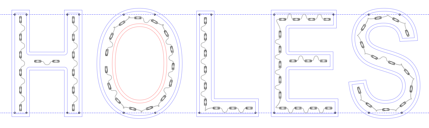
Here's an example of a 30" tall channel letter set with two rows of mounting holes along the top and bottom, with a 1" offset from the return, and 1/2" holes along the left and right of each stroke.

Please Note: if you want to add another set of holes that are a different size, then you must run the tool again and select the new size.


The mounting holes and the crosshairs will be added on different layers, and therefore can be exported selectively.


Previous  Next
Was this helpful?          

Copyright (C) 2019-2023 Principal Lighting Group, LLC