|
|
Previous Next
8.5 Arrange MenuAlign ToolsLED Wizard 8 contains several alignment tools to help with basic design and layout tasks.
Aligns the objects to the left, center or right boundary. For a text object, the alignment is changed only.
These commands align the objects to the top, bottom or vertical center of the group.
These commands align the objects with respect to the layout itself.
This command will align the objects to a common center point, so they all appear on top of each other. This is only useful with shapes that have nothing in the center. Distribute Tools
This will set the vertical space between graphics in a group to be the same, while keeping the current height of the group the same.
This will set the horizontal space between graphics in a group to be the same, while keeping the current width of the group the same. Step and RepeatThis is a very versatile and productive function that enables you to create and position multiple copies of an object or Group, as well as create sequencing of numbers. It is more efficient than Duplicate or Copy and Paste because you can create large numbers in one step and position them in a customizable grid. Start with a selected object or Group, which can be a populated object or Group, and then select Step and Repeat from the Arrange Menu and then Distribute. The property bar across the top of the layout window will change as follows.
This example shows 8 Copies of the selected object, in a grid with 4 copies in the horizontal direction (H Repeats) and 2 copies in the vertical direction (V Repeats). H Step and V Step are the values for the distance between the Bounding Box of each item. 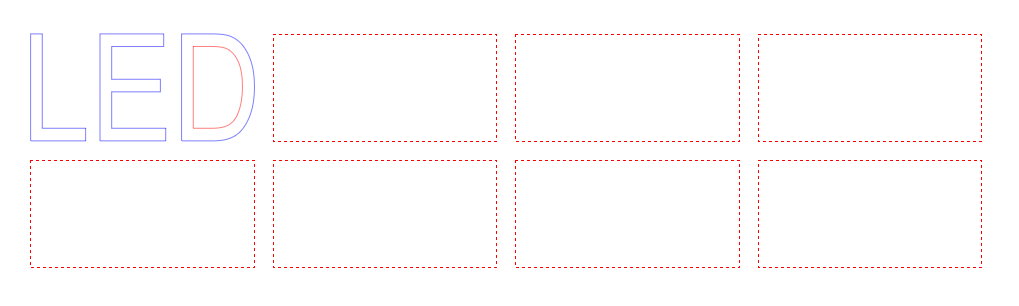
To use the numeric sequencing feature, sometimes called Variable Data or Variable Data Printing in the printing industry, enter the number that you want to sequence with the # sign. 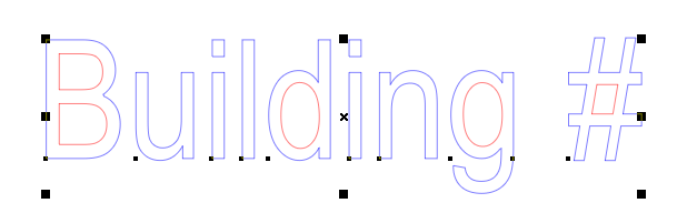
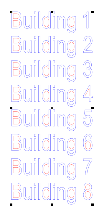
Then in the property bar, set the number of Copies and how many you want on the horizontal and vertical axes. In this case, all the copies are vertical, and the # sign becomes a sequencing number.
Group ToolsGrouping of elements in a layout is a fundamental task in LED Wizard, and there are several different Grouping and Ungrouping options. With the default Allow Auto Grouping turned on, to make a Group, you simply draw a box around the objects when you are using the Layout Tool. You can also create a Group or add to a Group using SHIFT+Click on the items you want to add to the Group. Groups can be nested, meaning there can be sub-groups within larger groups. How your design is grouped can be important when you go into Powerflow to make an LED Layout. A Group is treated as one object when you populate, in terms of the module used and the density guidelines applied. Therefore it is recommended that you Group items according to how you want to populate them. For example, here we have two letter sets, one at 48" tall and the other at 24" tall. These should be grouped separately for population. The first line, "COMPANY NAME" would be populated with a medium or large module, while the "TAG LINE" text would be populated with a small or mini module. Grouping these together and going into Powerflow in one step will result in the wrong module for one of the lines.
The Combine function is different from Grouping, and it's important to know the difference, especially as it relates to LED population and Statistics. Using this same example above, you would want each letter to be its own object so that you can generate a Stats object for that letter, such as how many modules, watts, etc. To do this, you would Group those letters together. If you Combine the letters together, you will have just one object, and therefore one Stat object for the whole line of text. One final note here: imported files vary widely in how the data is organized. Sometimes various items are Grouped or Combined together in haphazard ways, such as one or two of the smaller letters with one or two of the bigger letters in our example. This can make populating and generating meaningful stats difficult. Please also read the sections on [[Break_into_Loops]] and [[Break_into_Outer_Loops]] to further understand how to break combined objects down so that you can Re-Group or Combine them in a more logical way. Sometimes just Ungrouping isn't enough.
Select Ungroup when you no longer want multiple parts to be treated as one unit. This will Ungroup just one level if you have nested groups.
This command will ungroup all objects in the layout with a single command. Clipping paths are also ungrouped if you wish. This will Ungroup all nested groups to their individual elements.
This will make a group out of the current selection. This is only needed when the Auto Grouping option is turned off.
This groups all graphics in the layout into a single group. Group All LED ObjectsThis will make a group of all the LED objects in the layout.
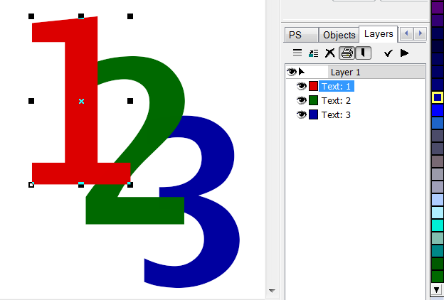
This command will group all objects that have the same fill color as the current selection.
This will make Groups of all the objects with the same colors. Group LayerThis command will group all objects that are on the same layer. LockedThis indicates that the object is locked and cannot be moved or deleted, just selected. Use this function when you don't want to inadvertently move or edit an object in your layout. EditableThe Editable option means that you can't select the object except by using the Layers tab. This is helpful working with complex designs and background elements. Select Only by Edge ClickWith this checked, the object can only be selected by clicking on the edge (outline). The normal selection behavior lets you click anywhere inside the bounding box of an item, but in the case of shapes, borders, cloud signs, etc., you may not want to do this because other design elements may be inside this bounding box. Therefore this option may make it easier to select these other elements because it doesn't try to select the outside object. This option is set per object; it is not a global setting for all objects in the layout. Allow OptionsThe Allow submenu lets you determine what type of changes are allowed on the selected object: ScalingThis toggles whether scaling is allowed. SlantingThis toggles whether slanting is allowed. RotationThis toggles whether rotation is allowed. Please note: these changes are NOT allowed on populated objects, except for the new Population Scaling Tool tool. Break Into LoopsThis command will break the selected graphic into its individual loops, including inner loops. Some artwork may be Combined into one large graphic, in which case it may be necessary to break it down into its individual components. Perhaps there is a letter set and a cabinet, and you want to populate them with separate modules. Your first approach should be to simply Ungroup the artwork. Remember that there can be Nested Groups, so you may have to Ungroup several times. But if the artwork is combined into a single object, then you will have to Break Into Loops, or to preserve inner loops, Break Into Outer Loops. Break Into Outer LoopsThe Break Into Outer Loops command will take the selected object and make each loop a new object, keeping inner loops with the enclosing outer loop. This is critical for LED layouts. For example, if you import a letter set and the artwork was combined into a single object, you can use Break Into Outer Loops to break it down into individual letters. 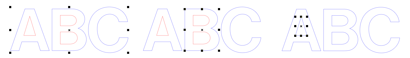
The graphic on the left is the original import as one combined object. If you use the command Break Into Outer Loops, you will get three individual letters as shown in the middle graphic, which is what you want. If you use Break Into Loops, you will get the graphic on the right, where the "A" is actually two separate loops, and the "B" is three separate loops. Note too that the Loop Directions are now wrong for these letters, since the inside loops are not Combined with the outside loops. (Inside Loops should be red, which are counter-clockwise.) If you import a letter set where all the loops are separate and not combined into letters, then you can use the Combine command on each letter where there are multiple loops and/or internal loops. Combine also Reorders Loops. CombineThis command will Combine all the elements of the selected group into a single graphic. Commbine is more permanent than making a Group. When you Combine multiple loops or objects together, it becomes one object, and therefore has a single Stats object. A Combined object cannot be Ungrouped. To break down a Combined object, you must Break Into Loops or Break Into Outer Loops. In LED Wizard 8, a combined object will be populated as a single object, and have one Stat object associated with it. Perhaps this is a logo with multiple components, or a cloud sign. But as a general guideline, a letter set should be broken down to its individual letters. 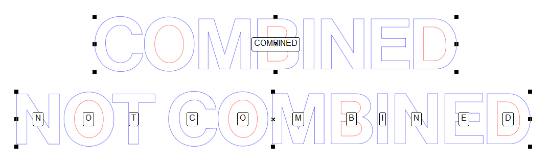
Close All LoopsThis command will close all open loops in the selected graphic. There are multiple ways to close loops, and this function should be used when the loop ends are very close together and you want to close all loops in one step. If you want more precision in closing loops, then you should use the Vector Edit Tool and the option Vector - Join St/End Point. Or if you want to close loops one at a time, you can also use the Close Loop function in the Loop Edit Tool. If you have Exploded Data, then you should use the Unexplode Vector Paths tool or the Data Clean Up Tool. 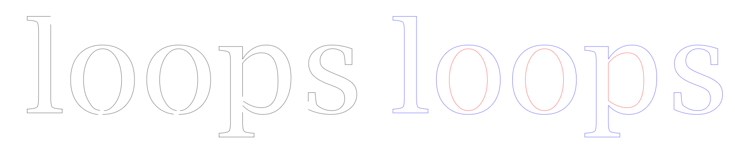
Remember that open loops are shown in black when in Wireframe mode with Show Loop Directions on.
Remove All Inner LoopsThis command will remove all inner loops from the selected graphic. An application of this feature might be a cloud sign, where there are internal loops that you want to remove. 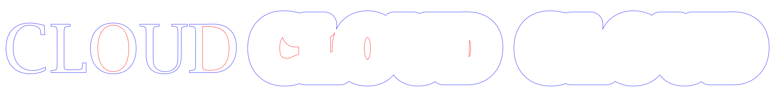
You can also use the Loop Edit Tool to select and delete loops individually. Horizontal MirrorThis command will allow you to mirror an object horizontally. 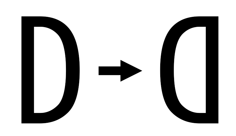
If you want to keep the original, then first Duplicate it before you use the Mirror command. Vertical MirrorThis command will allow you to mirror an object vertically. 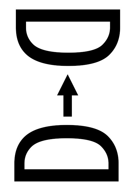
If you want to keep the original, then first Duplicate it before you use the Mirror command. Z Order ToolsThe Z Order Tools let you change the layer of the selection relative to other objects in the layout. The Layers Tab will show the vertical order of the layers, and you can move layers up and down through that interface as well by clicking and dragging a layer up or down.
Move to LayerThis command allows you to move an object to any layer without having to drag and drop in the layers list, which can be difficult with very complex layouts. 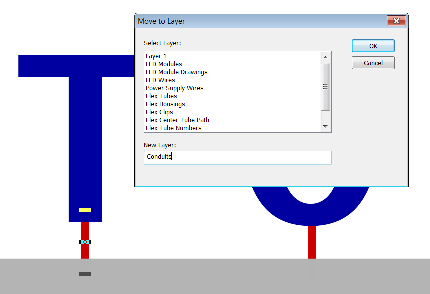
In this example, we have conduits going from the letters to a cabinet. Here in the Move to Layer dialog box, we have created a New Layer called Conduits. Each conduit will be placed in this layer, which in the Z Order, will be on the bottom, behind the letters and behind the cabinet. To TopThis moves the selection to the top of the z-order in the layout. The shortcut key for To Top is PgUp (PageUp). To BottomThis moves the selection to the bottom of the z-order in the layout. The shortcut key for To Top is PgDn (PageDown). Move One UpWhen there are many overlapping objects in the layout, use Move One Up to move a selected piece up one layer. Move One DownWhen there are two or more objects in the layout that are overlapping, use Move One Down to move a selected piece down one layer. Previous Next |


 As a general guideline, LED Wizard needs closed loops to create an LED population. However, if you have artwork that contains open loops, then you can go into PowerFlow and convert the open loops to a guide path. But this creates the modules directly on the path, and not a single or double run inside of a channel letter, for example.