|
|
Previous Next
8.3 View MenuZoom commandsYou can zoom the layout in and out with the right mouse button. Right click in the layout and draw a box to define the new workspace view. Right click and release the button without moving to zoom out. To pan the workspace, hold the space bar while moving the mouse.
This command lets you zoom in closer. Use the left button to draw a box that defines the new zoom level.
This command zooms out to the last zoom level.
This command zooms to the entire set of graphics in the layout. This will include objects that are outside the dotted line rectangle, which is the overall Layout Size.
This zooms to the selected object.
This zooms to the layout itself. PanHolding down the Space bar while moving the mouse will pan. This command itself does nothing and it's only here to show that the Space bar activates panning. Right Mouse Button ZoomingIn addition to these Zoom tools, remember that drawing a box with the right mouse button will Zoom In. Holding the mouse still and clicking the right mouse button will Zoom Out. Zooming using the right mouse button is nested, meaning you can have different zoom levels. Zooming in this way works in all operating modes. Mouse Wheel ZoomingIf your mouse has a wheel, then you can also use this for Zooming. Rolling the mouse wheel away from you Zooms In, and rolling the wheel towards you Zooms Out. You might want to use this approach along with the Space bar to adjust the exact position of the zoom. Toolbox menuHigh Color Toolbox EditorThis modeless dialog box lets you customize the high color toolbox. You can select from any number of predefined configurations, drag icons to the toolbox to add them, and even recreate the toolbox using a different size for the icons. ConfigurationThis list represents all of the toolbox configurations available. The Icons folder contains two files for every configuration: A .hci file containing the icons rendered as transparent bitmaps, and a .tbx file, containing the set of menu commands for the toolbox. Icon SourceThis lets you create a totally different icon set to use, which determines the actual look of each icon. To create an alternate icon source file, save the loaded layout to a different name in the special Icons folder (which is in the LED Wizard program folder), then restart the software. NewPress this button to create a new named toolbox configuration. RemovePress this button to remove the selected toolbox configuration. RenameUse this to rename the current icon configuration. This renames all associated files located in the Icons folder. Menu CommandsThis list is the all menu commands in the software that can be assigned an icon and/or placed in the toolbox. Not every command has an icon, but you can easily create one yourself. The procedure for creating your own icons is simple:
Icon SizeThis is the size of the icons in pixels. The Margin setting will decrease the actual rendered size by the corresponding percent of this icon size. MarginThis adds a margin around each icon so they don't bunch up too much and are easier to read. GrayscaleThis option will make all icons grayscale, if you prefer to not have our colorful icons interfere with the color perception of your designs. Highlight UnassignedThis draws a small "U" next to all graphics that don't have a menu command associated with them. Default ToolbarsThis text box lets you define the default toolbars that appear docked at the top of the window when this icon configuration is selected. You enter here the names of the icon groups that identify the toolbars you wish see docked at the top of the window, separated by semicolons. The names must be exactly match the group names for them to appear. Render All IconsThis command converts all the icons defining in the current layout to a set of small transparent bitmaps which are directly used in the high color toolbox. Custom ToolbarsThis menu lists all the custom toolbars as defined by the Group naming of icons in Tools | Options | High Color Toolbox. Every icon with the same Group name is automatically part of a custom toolbar that you can show or hide with this menu. Drawing ModeThese commands enable the new anti-aliased drawing mode.
Switch into the standard drawing mode. This is not as smooth as Anti-alias mode, but it is usually faster. Standard Plus Anti-Alias Drawing Mode
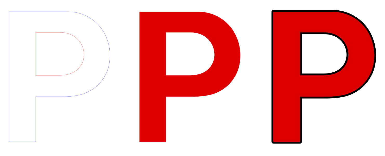
This mode is the new high quality mode, which creates a much smoother look for vector graphics. Use Standard When Show Fill Colors is OffCheck this to revert to Standard mode when in wireframe mode, which will be faster. RefreshUse this tool to redraw the screen. Sometimes the screen does not update fast enough or automatically, and you can use the Refresh tool to do this manually. This does not make any changes to the underlying layout. The shortcut key for Refresh is W. Show Fill ColorsThis toggles the display of fill colors in the design. The Color Palette along the right edge of the screen will toggle on and off with this option as well. When Show Fill Colors is off, then Wireframe mode will be on, which shows the Loop Directions of blue for a closed outside loop, red for a closed inside loop, and black for an open loop. The shortcut key for Show Fill Colors is F3. Show Stroke ColorsThis toggles the display of strokes in the design. A stroke will not be drawn in wireframe mode.
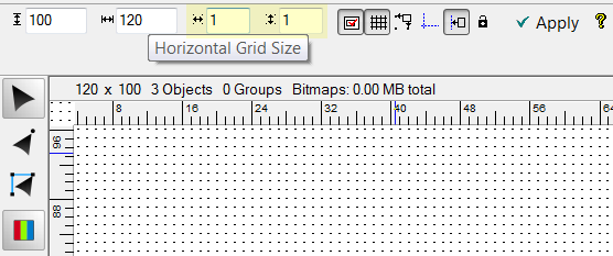
Show GridWhen Show Grid is selected a series of dots will be displayed in the background. You can change the size of the grid points by selecting Layout Properties from the Layout Menu or by double clicking in an open space in the layout area.
You can then enter the increments for both the Horizontal and Vertical axis. Once you select OK, the grid will be displayed with the new information. You can also select Snap to Grid, which will only allow you to move an object from one grid point to the other. When you use Grid Mode as an LED layout option, this will create a grid with the horizontal and vertical axes that you define. Show GuidelinesWhen the Show Guidelines command is selected, the guidelines are hidden or shown, depending on whether the command was checked or not. If it was previously checked, then the guidelines will be hidden, and if it was not checked, the guidelines will be shown. The guidelines are always active whether or not they are shown. Show RulersThis option will show or hide the Rulers on the top and left side of the workspace window. Note that you must have the rulers on to create guidelines. Rulers will be displayed in the Units of Measure that you have selected in the Options dialog box in the Tools Menu. Show Loop DirectionThe Show Loop Direction command is a toggle command, meaning that when you select this command, the loop direction will be displayed if it isn't already, or it will be turn off if it is displayed. See Reorder Loops for more information. The Show Loop Direction option should normally be checked. Show Job Color PaletteSelect this to show or hide the palette at the bottom of the window that contains the current job colors and lets you set fill color, stroke color and stroke width parameters. 
Show Side BarThis will toggle the side bar on and off. The sidebar is on the right of the screen and contains various tabs, such as PowerFlow on the top and PS on the bottom. In normal operation, the side bar should always be on. Show Info BarThis toggles on and off a horizontal bar below the property bar area, which shows various properties of the select object(s), such as the name, size and position. Show Help BarSelect this command to turn off or on the Help Bar at the bottom of the screen.
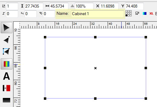
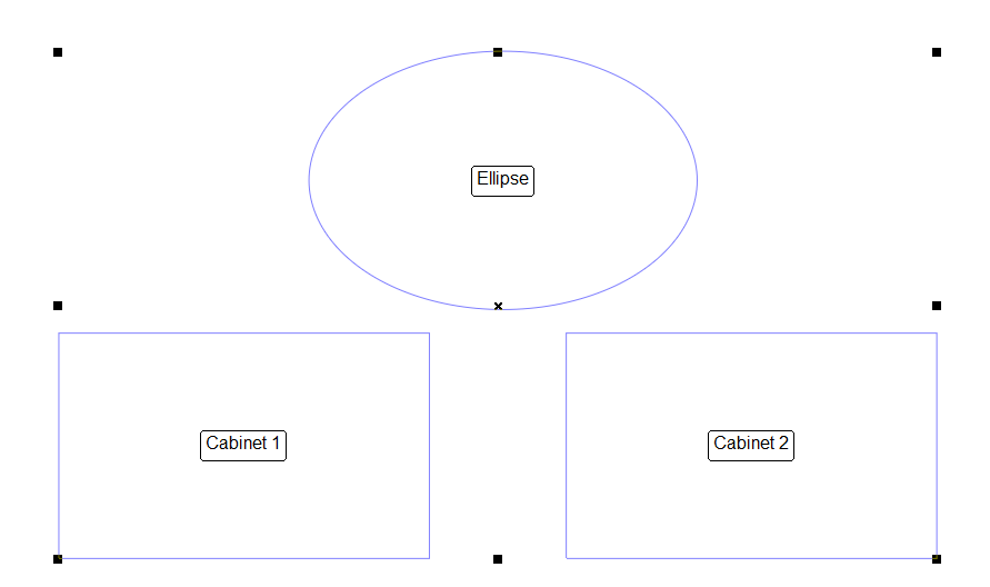
The Help Bar will give you context sensitive help regarding the current tool or function. Once you know how LED Wizard works, you may not need the help messages, and turning the bar off will make your workspace larger. But sometimes you might forget a particular keystroke or option for a feature, and the Help Bar can come to the rescue. Show Group Member NamesThis command toggles the group member names display, which is used in the Assign Letters Tool. An object has a Name, which is displayed in the Property Bar when that object is selected. You edit the Name in this field.
With this option checked, that Name will be displayed in the center of each object in a Group.
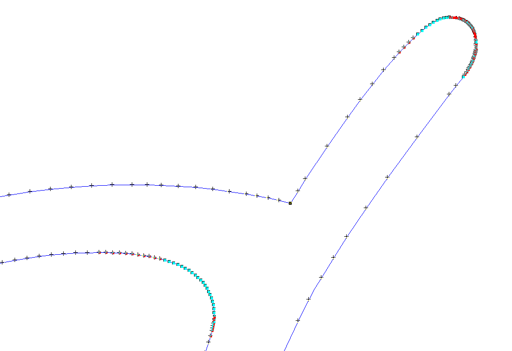
After you have populated an object, you can use the Assign Letters Tool to give each object a Name. If you have imported text, then this is how you will enter each letter, which will then be used in the Stats. Highlight Small VectorsSelect this to highlight all very small vectors, which can help find problem areas in some files.
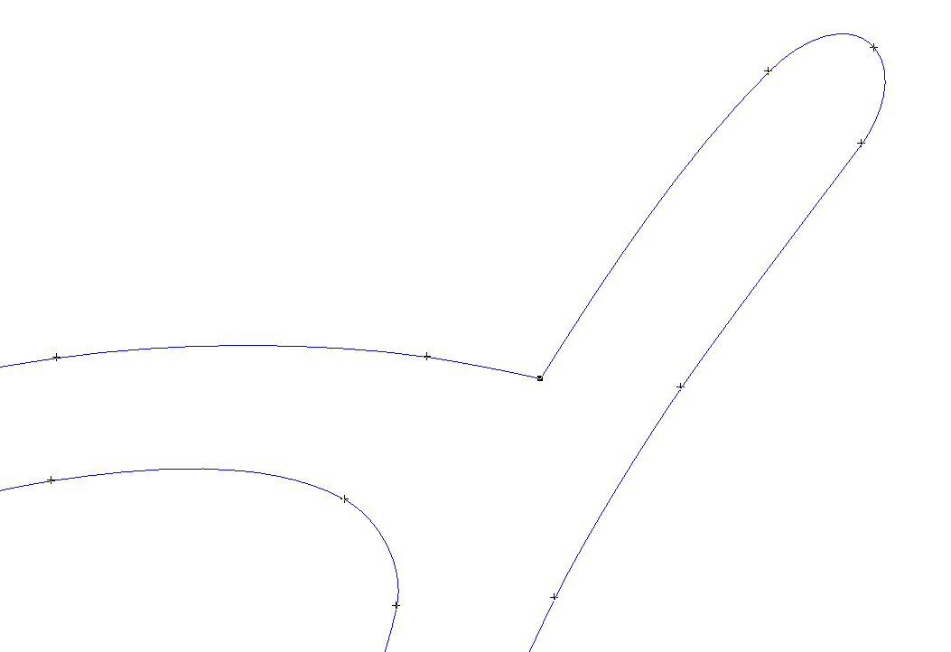
In this example, you can see some points highlighted as blue, which are non-tangent very small vectors, and some points highlighted in red, which are tangent very small vectors. Depending on various parameters of an imported file, sometimes there are "very small vectors" that should be edited out using one of our tools. The Data Clean Up Tool is the obvious first choice, but the Alt-Smoothing function (Vector Edit Tool) is also very effective at removing extra points and smoothing out the data. Using the function Recreate with Bezier Curves (Tight) (available in the Data Clean Up Tool or standalone in the LED Menu), we get the following:
It is a good idea to keep this option turned on, since this kind of data can increase file size and cause data or population problems. Transparent BackgroundThis command switches the transparent background mode off and on. With it on, there is no background color to the layout. Instead, a checkerboard is displayed beneath all graphics, which allows transparent bitmaps and objects filled with the background color to be seen.
Reset Toolbar LayoutSometimes the Toolbars in LED Wizard can inadvertently be changed or edited, and this can make it difficult to access certain functions. The Reset Toolbar Layout function will return the toolbars to the original factory settings. Previous Next |
