|
|
Previous Next
8.13 Modify MenuThe Modify Menu contains many commands that enable you to edit LED modules in your layout. All of these commands assume that you are in the PowerFlow operating mode and already have some modules in the layout. Most of the Modify Menu commands have shortcut keys, and these are indicated in each topic as well as the Shortcut Key Reference summary. Select All Modules in Run - Ctrl+ASelects all modules in the current run. A "run" is defined as a string of modules connected by wires. When there is a break in the wiring, that constitutes two separate runs, even if the modules are close together. When a run is "selected," the modules will be highlighted in a darker outline. 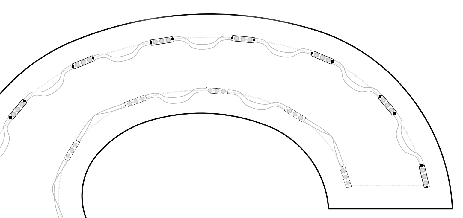
Select All Modules in Letter - Shift+ASelects all modules in the current letter. 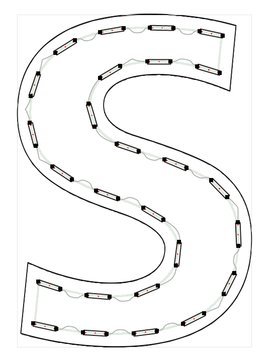
Among many other options, one of the more common reasons to select all modules is to copy them to another letter (Shift+A selects and copies all modules to the Clipboard). You can easily do this by then clicking on another instance of this same letter and pressing Shift+V. The modules selected in the original letter are then copied to the new letter. Make sure that the destination letter does not have any modules in it already. Select Stroke - Alt+Shift+ASelects the modules in the current stroke, which are defined as modules that don't make sharp turns. This option is available so that you can edit selections of modules without going around corners. Editing a selection of modules includes functions such as Increase Density, Decrease Density or various Rotation options. 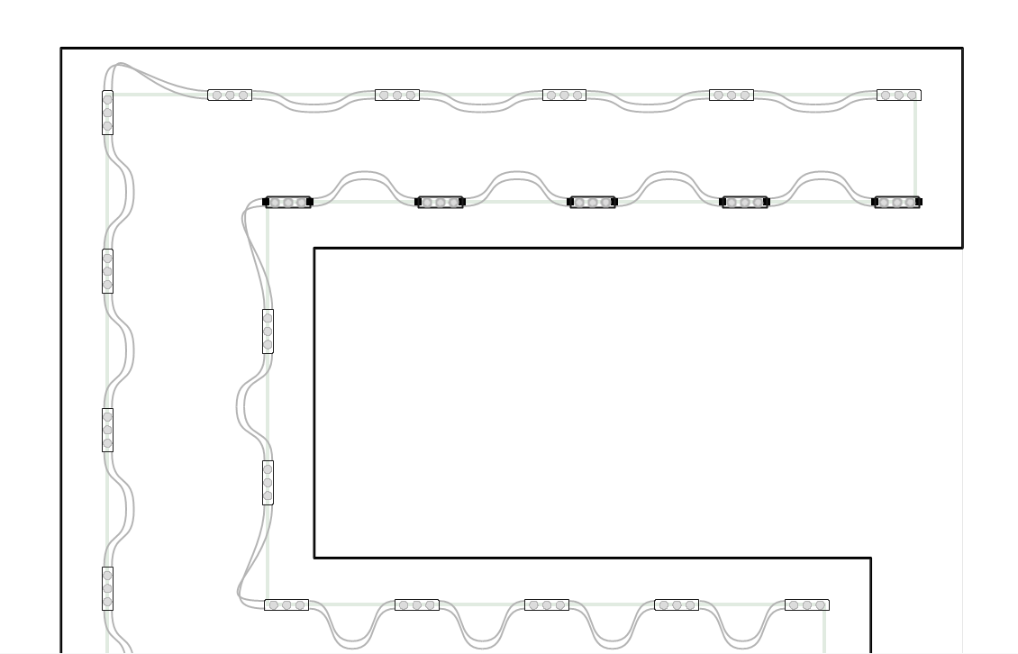
Add Run to Selection - Ctrl+Shift+AThis tool adds the current run to the set of selected modules. 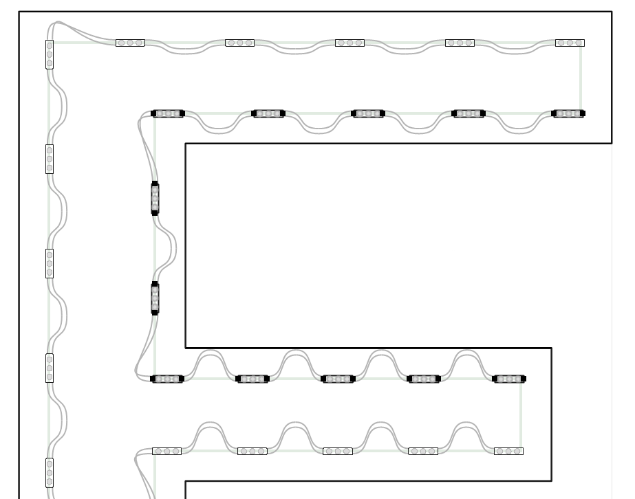
This example continues from the previous topic, Select Stroke, and selects the rest of the modules in that run. Rotate MenuThe commands in the Rotate menu only change the secondary rotation angle for a module. The secondary rotation is independent of the primary rotation, which is set by the guide path for the modules. 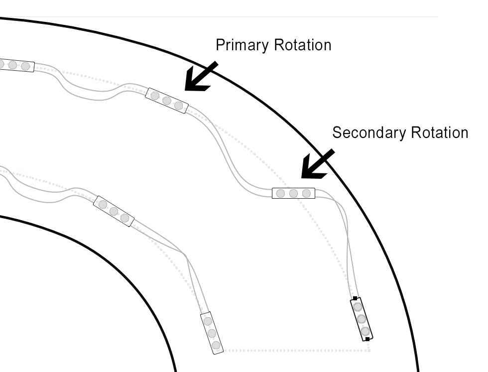
All of the commands in the Rotate menu are available on single modules and selections of modules. Reset Primary Rotation Angle - Shift+Ctrl+0This resets the primary rotation angle of the selected modules, which is determined by the guide path. Reset Secondary Rotation Angle - Ctrl+0This resets the secondary rotation of the selected modules, which can be adjusted by one or more of the options here in the Rotate menu. Alternate Rotations - UThis will rotate the selected modules so they alternate, changing normal rotation by 180 degrees with every other module. Note that the 180 degree rotation has the effect of alternating the wiring. 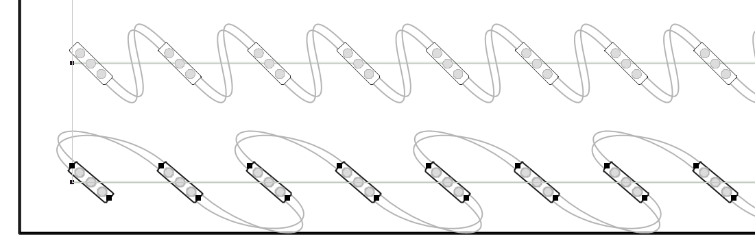
This is not a property, but rather a one time operation. However, you can respace, add or remove modules and this alternating rotation will be preserved when possible. Rotate 90 degrees - TThis rotates the selected modules left by 90 degrees. 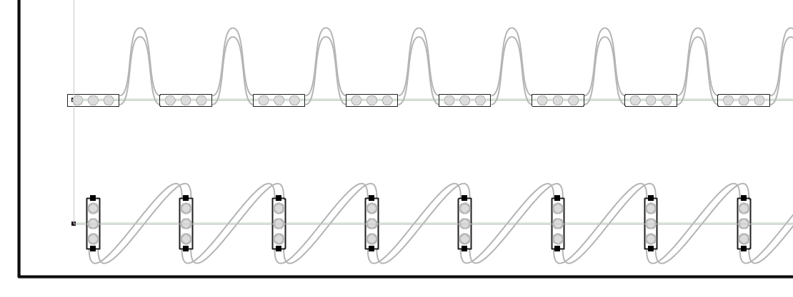
Rotate 45 degrees - Ctrl+4This rotates the currently selected modules by 45 degrees. 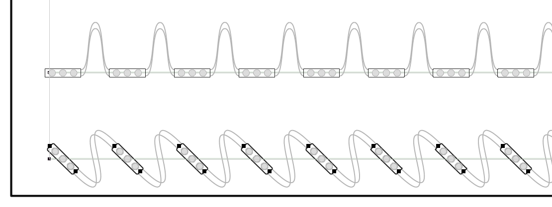
Rotate 45 degrees - Alternating - Ctrl+5This rotates the currently selected modules by 45 degrees, alternative the angle with each module. 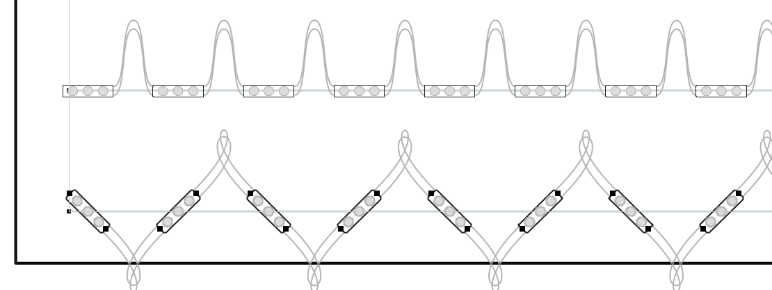
Rotate Counter-Clockwise (Left) - Ctrl+XThis rotates the selected modules left by 5 degrees. When a selection is rotated, new modules are inserted when necessary. 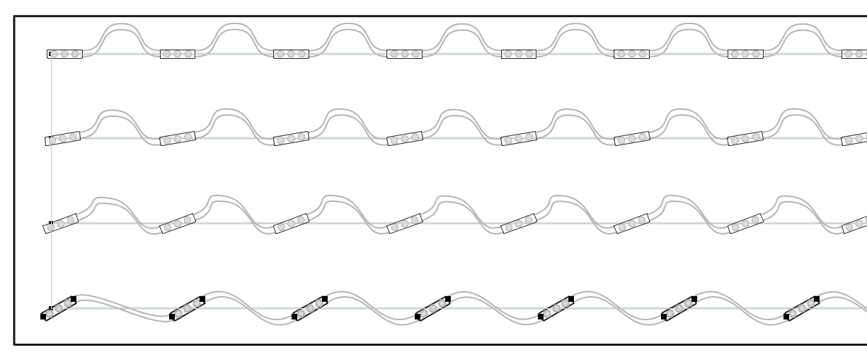
In this example, the top row is the original with no rotation. The second row is rotated twice at 5 degrees each for a total of 10 degrees. The third row is rotated four times for 20 degrees, and the fourth row siz times for 30 degrees. If you continue to rotate modules in this fashion using this tool, it will automatically insert modules into the selection so that there are no red wires, as in this example, a continuation of the above: 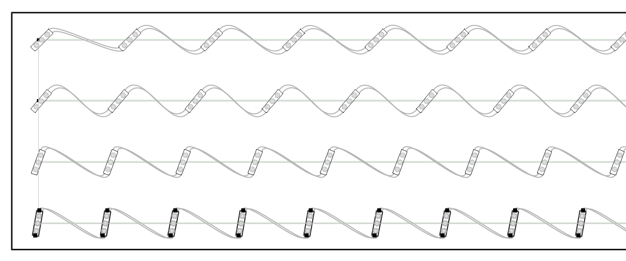
If you continue rotating to the point where the modules are perpendicular to the stroke, then you can consider alternating the wiring using the function Convert to Perpendicular Alternate Rotated, as in this last line. 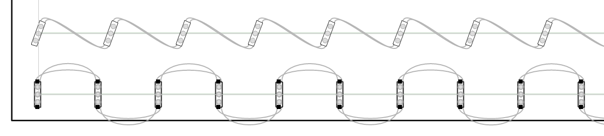
Rotate Clockwise (Right) - Ctrl+CThis rotates the selected modules right by 5 degrees. When a selection is rotated, new modules are inserted when necessary. Please see the complete topic description for rotating modules the other direction: Rotate Counter-Clockwise (Left). Flip Primary Rotation Angle - Ctrl+FThe Ctrl+F key will rotate the selected modules' primary rotation angle by 180 degrees. 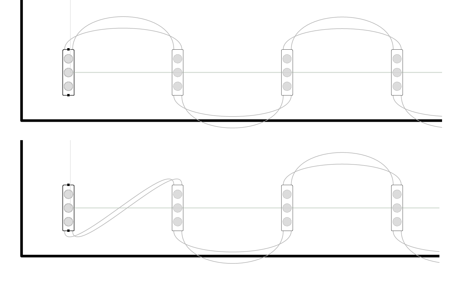
Flipping a module by 180 degrees in this way changes how the module wired, but not the actual module rotation. Flip Secondary Rotation Angle - FThe F key will rotate the selected modules' secondary rotation angle by 180 degrees. Convert to Perpendicular Alternate Rotated - Ctrl+UThis command converts the selection into an alternating 90 degree rotation pattern.
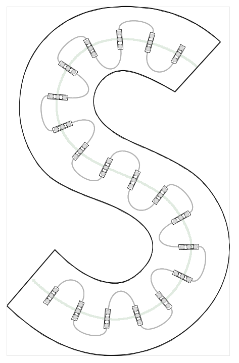
Depending on the length of the wire and the module spacing, this layout option can give a similar number of modules as two runs. Once you have created a run using the Perpendicular Alternate Rotated command, be aware that you can make a selection and use the commands to insert or delete modules from the selection.
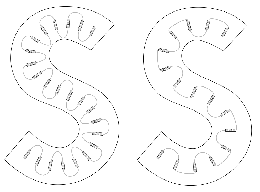
Here we have taken the original layout and added modules to the "S" on the left using the Increase Density command (shortcut key "W"), and then deleted modules to the "S" on the right using the Decrease Density command (shortcut key "R"). Density MenuThe Density submenu contains commands and keys for working with the density of modules. The term "density" can mean different things, but for our purposes here, it means:
LED modules are generally defined by their linear metric. A module may have a maximum linear spacing of two modules per foot, which is 6" from the center of one module to the center of the next module when the wire is pulled tight. But this module may populate at 2.5 or 3 modules per foot, depending on the depth of the sign. Most of the functions in the Density Menu have to do with the linear density of modules. But even if we adjust populations based on the linear density, the measurement of how many modules there are in a given area is really a better metric of "module density." A letter set that is populated at "Two modules per square foot" is more descriptive than a letter set that is populated at "Three modules per foot," because that says nothing about the stroke width of the letters. 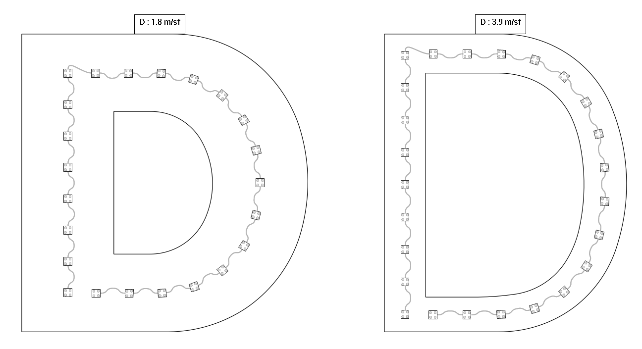
Here we have the letter "D" in Helvetica Bold and Helvetica Regular, same height of 50". The populations about both a little more than two modules per foot, but the first "D" shows 1.8 modules per square foot and the second "D" shows 3.9 modules per square foot. 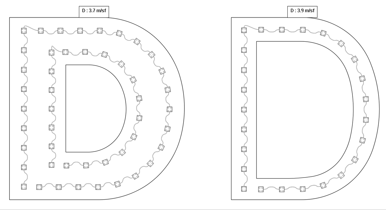
Now when we populate the first "D" with two runs, we get a more consistent 3.7 modules per square foot, as compared to the the second "D" at 3.9. If you have a set of letters that have a consistent stroke width, then you will get consistent modules per square foot readings when you have consistent modules per foot populations. However, if you have variable stroke widths, then you have to be more careful to maintain consistent brightness across letters, and you should consider looking at the [[Density_Segments]] feature. Increase Density - WAdding modules to a selection or run is easy with the Increase Density function. This will add a single module to the current selection, or the current run when there's no selection. If there are any red wires between modules, this command is an easy way to address that. Each time you click the icon or use the shortcut key "W," a module will be added (and the selection or run will be respaced). 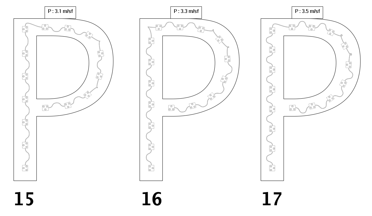
Here we start with 15 modules, then add one and two modules. In this example, we made a selection of all the modules. Increase Density For Entire Run - Ctrl+WPressing Ctrl+W will add a single module to the current run. Use "W" to limit this to the current stroke, meaning the part of the run around the current module that doesn't make sharp turns. Decrease Density - RDeleting modules from a selection or run is easy with the Decrease Density function. This will remove a single module from the current selection, or the current run when there's no selection. Each time you click the icon or use the shortcut key "R," one module will be deleted (and the selection or run will be respaced). 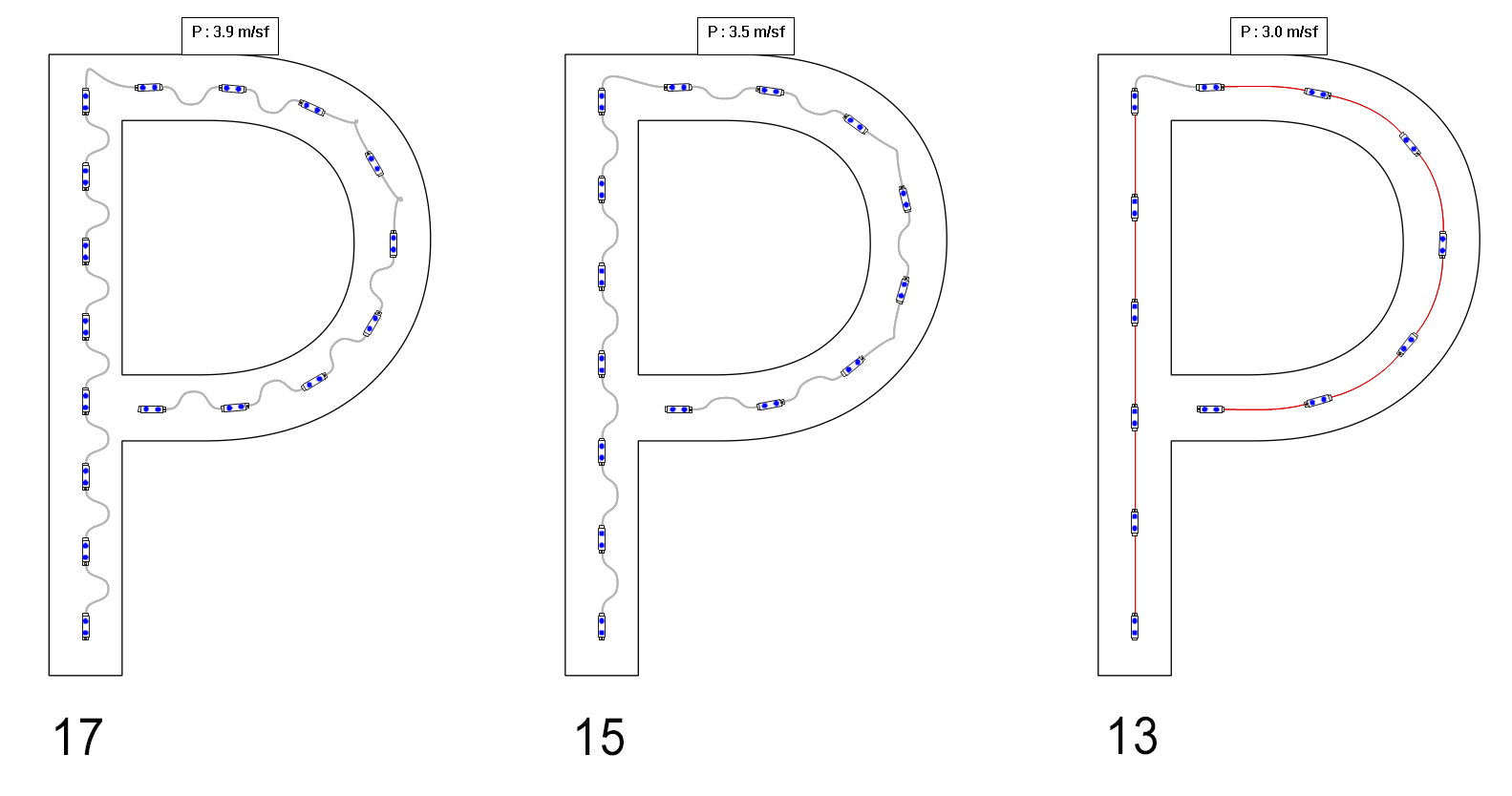
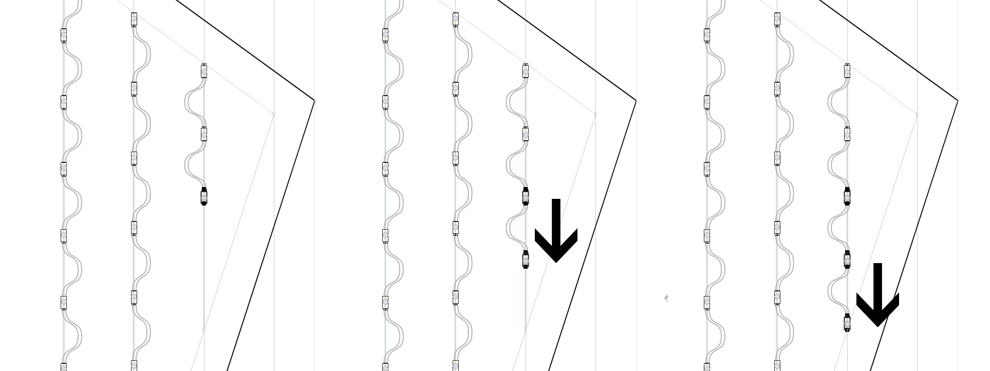
Be careful that you don't remove so many modules that you end up with red wires, as in the third example here. In some cases, you may want to use the least modules possible in a layout, and one way to do that is to remove modules using this command until you see red wires, and then add one back with the Increase Density command ("W") or Undo. Decrease Density For Entire Run - Ctrl+RPressing Ctrl+R will remove one module from the current run. Use "R" to limit this to the current stroke, meaning the part of the run around the current module that doesn't make sharp turns. Uniform Spacing - EEvening out the spacing between modules in a selection or run is easy with the Uniform Spacing function. This will repace all modules in the current selection, or the current run when there's no selection. As with Increase Density and Decrease Density, the end modules in the run or selection will remain in their current positions, and all modules in between will be adjusted. Note that when you increase or decrease density using "W" and "R," the modules are automatically respaced evenly. Therefore use this option "E" when you have the correct number of modules and you just want them evenly spaced. 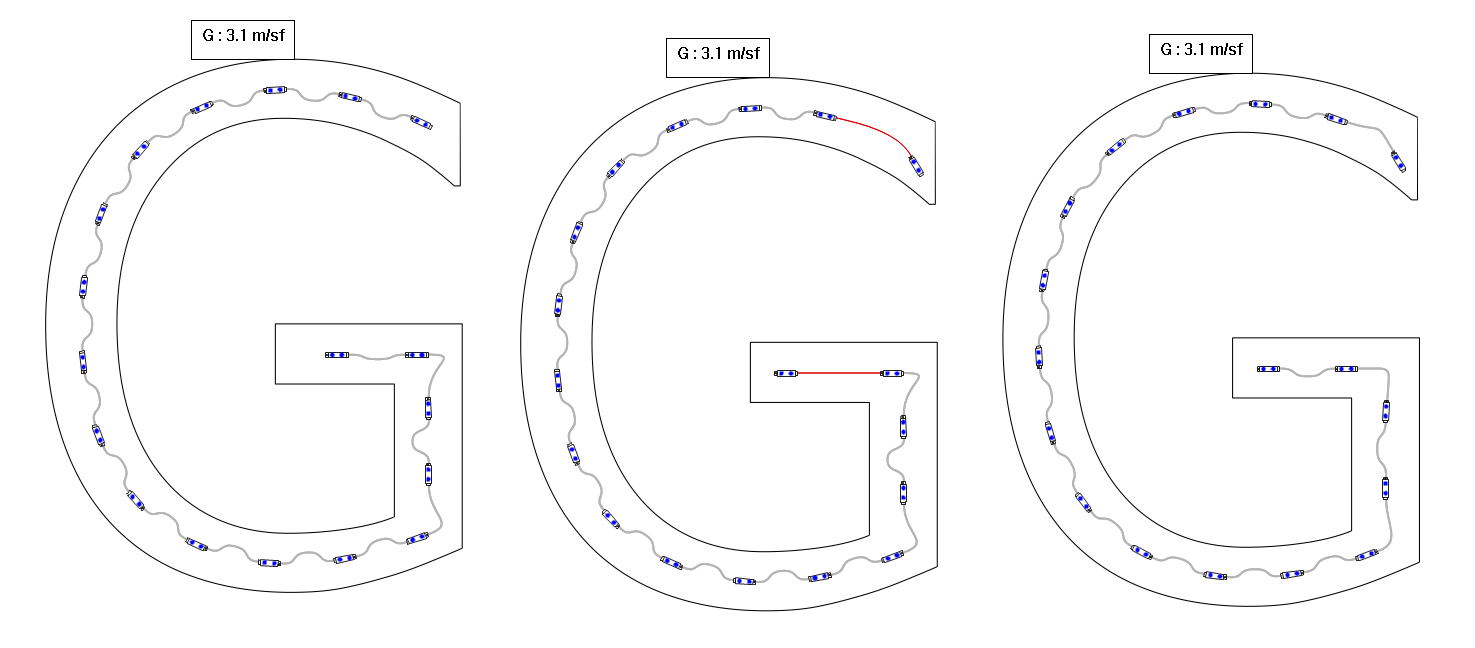
In this example, we want to get the modules deeper into the ends of the strokes. So in the middle graphic, we have moved the end modules, creating red wires. To get to the result in the third graphic, we selected all the modules and then used the shortcut key "E." Note that you can select all modules by clicking on one end module, then holding SHIFT and clicking on the other end module. Alternatively, you can use SHIFT+A to select all. Uniform Spacing For Entire Run - Ctrl+EPressing Ctrl+E will recalculate the space between the modules of the current run. "E" will be limited to the current run stroke, while Ctrl+E will respace the entire run. Add / Remove Density Segment - LThe "L" key adds or removes a density segment. This can only be used with the L key and not menu because the cursor position is used. Show Density Segments - Shift+LThis will show or hide the density segment display. This display is automatically enabled when using L to add or remove a segment. Clear All Density Segments - Ctrl+Shift+LSelect this or press Ctrl+Shift+L to remove all density segments. Append Module - GThe Append Module function will add a module to the end of a run, when the end module is selected. The new module will be appended using the same rotation and spacing as the last two modules in the run. Use the shortcut key "G."
Insert Single Module - IWhen editing a run of modules in PowerFlow, pressing "I" or left clicking when the cursor changes to a + sign will insert a module at the cursor position. This is most often used when you want to Insert a module in the middle of a run. If you want to add a module to the end of the run, then you can just click when the preview module is in the right position and this will add the module. The preview module is always attached to the mouse position and ready to be inserted when you click. 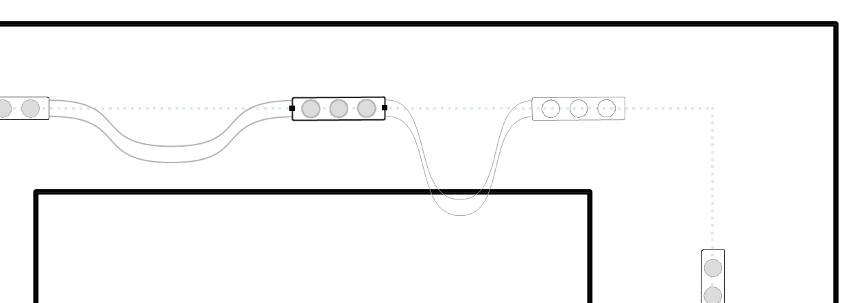
There is a special case for inserting modules, which is when the wire is red from having two modules too far apart. When you position the mouse over the red wire, the "preview" module will turn green, and you just click the left mouse button to insert a module into that position. 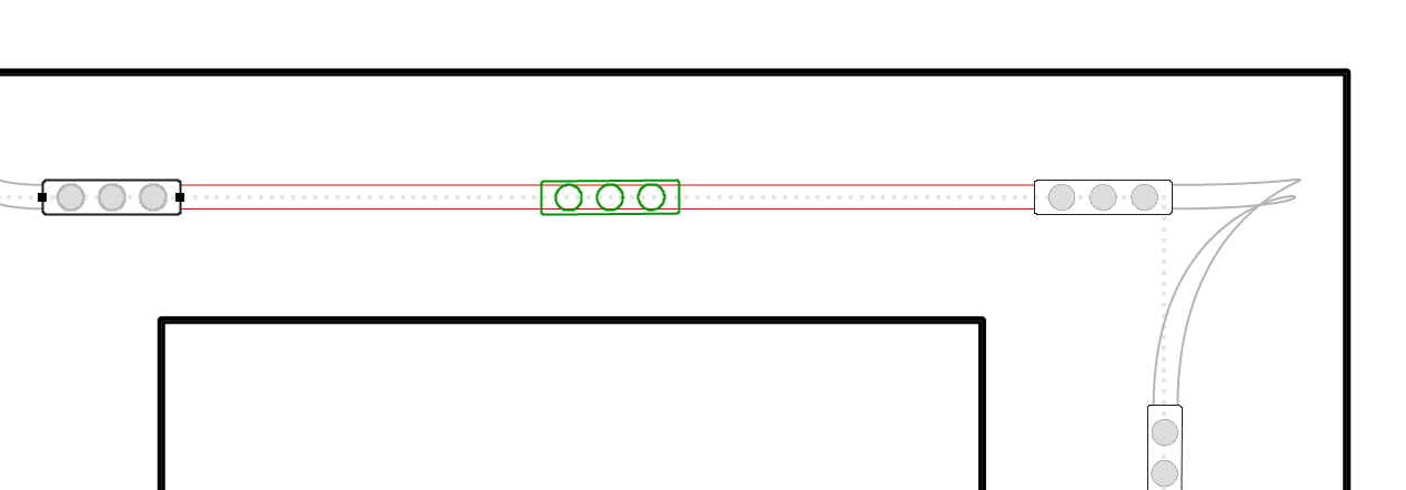
Mirror HorizontalThis function will take an already populated object and created a horizontal mirrored version of it 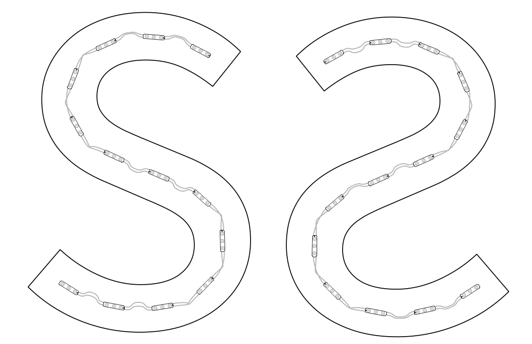
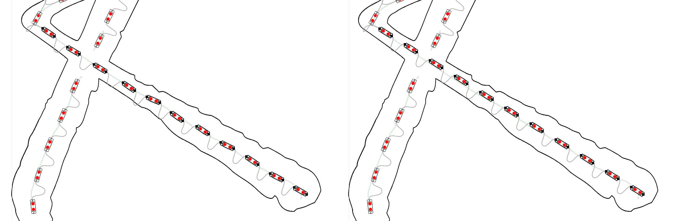
The left image is the original and the right image is the horizontal mirror. Note that the function does not make a copy as shown here, it just mirrors the original object. Mirror VerticalThis function will take an already populated object and created a vertical mirrored version of it. 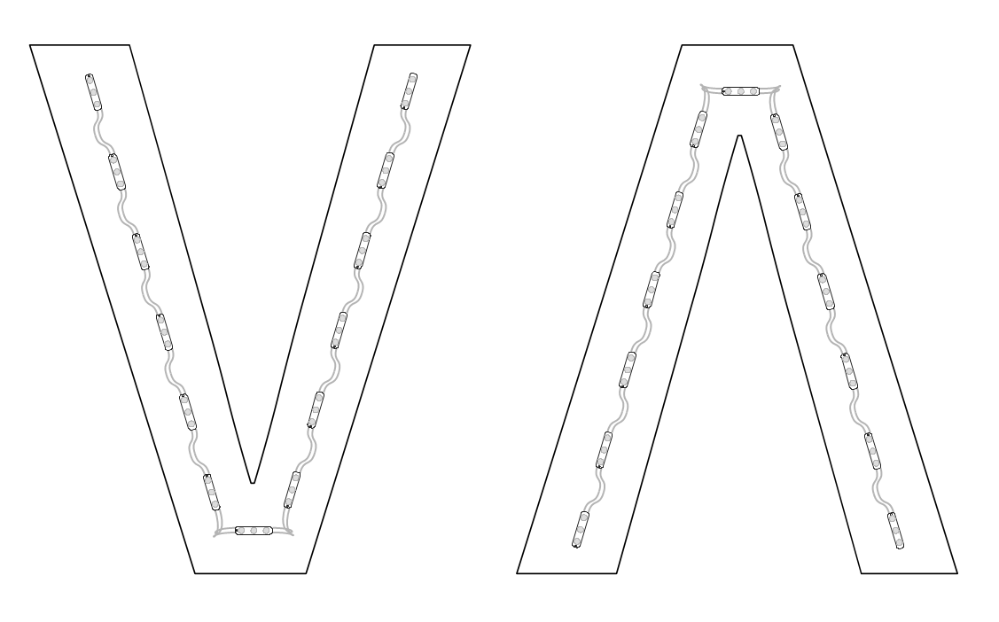
The left image is the original and the right image is the vertical mirror. Note that the function does not make a copy as shown here, it just mirrors the original object. Fill To Cursor - JPressing "J" will create a line of modules from the selected module to the cursor. The preview module position will not necessarily show where the new modules will be placed. 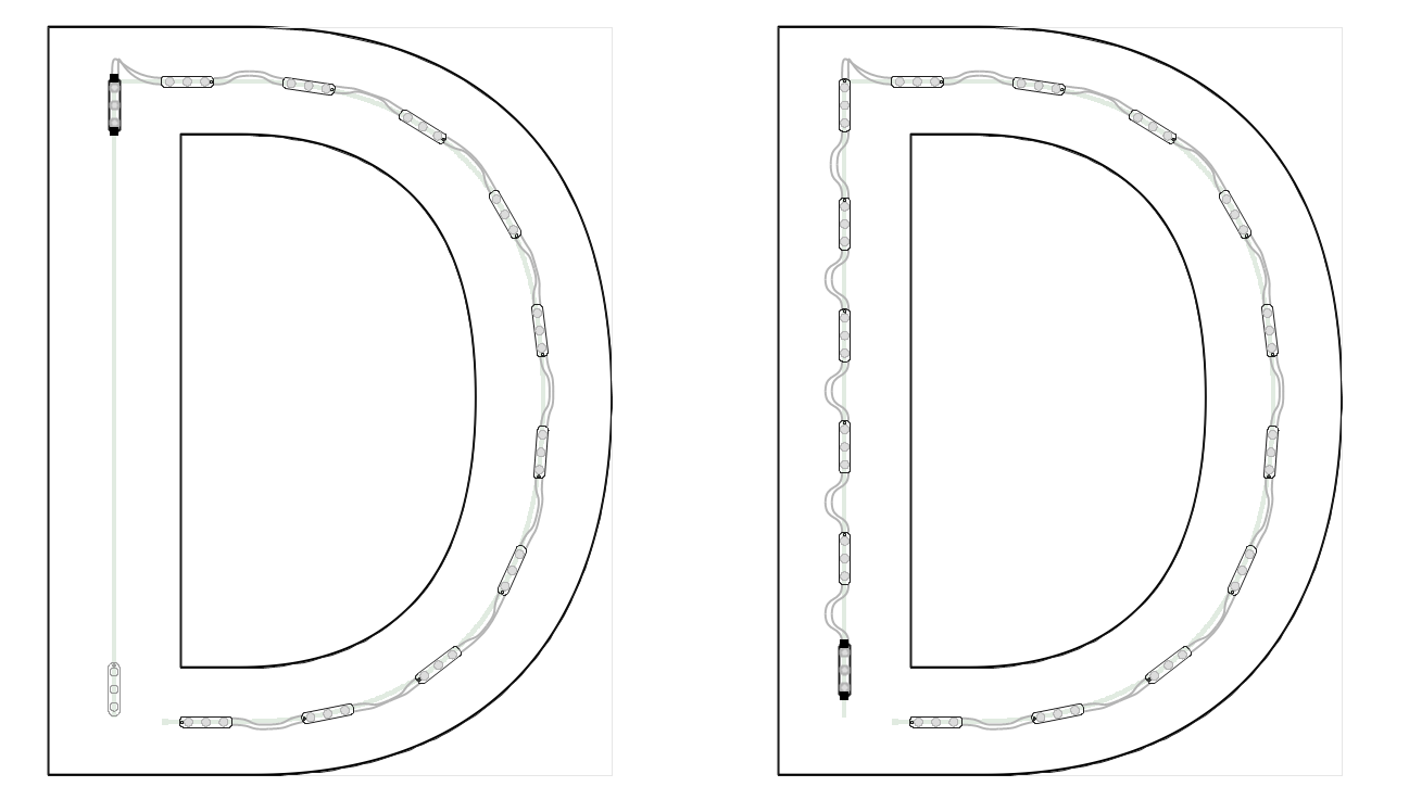
Break Run - OTo break open a run at the cursor, press the letter "O" key. You can control at which end of the module the break happens by placing the cursor nearest that end. Even though there is a menu item for Break Open, this is a function that you want to use with the shortcut key because the position of the mouse is important.
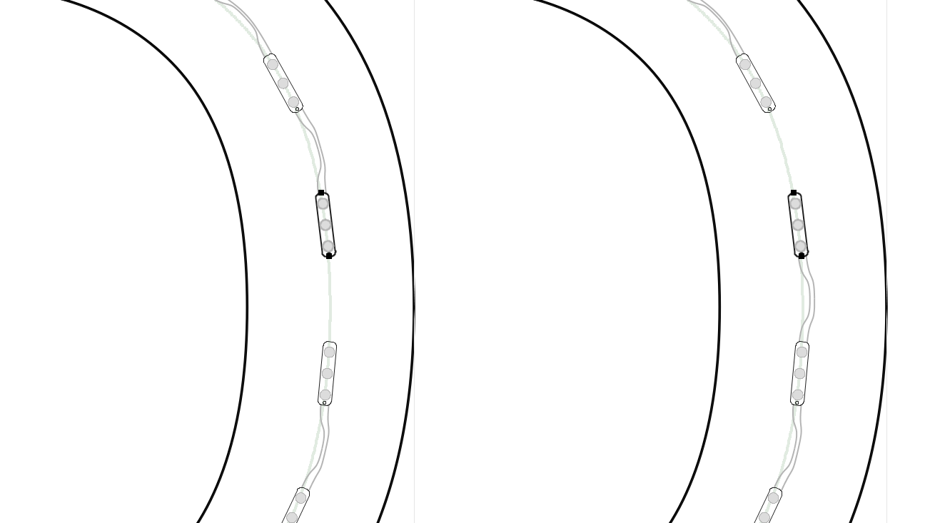
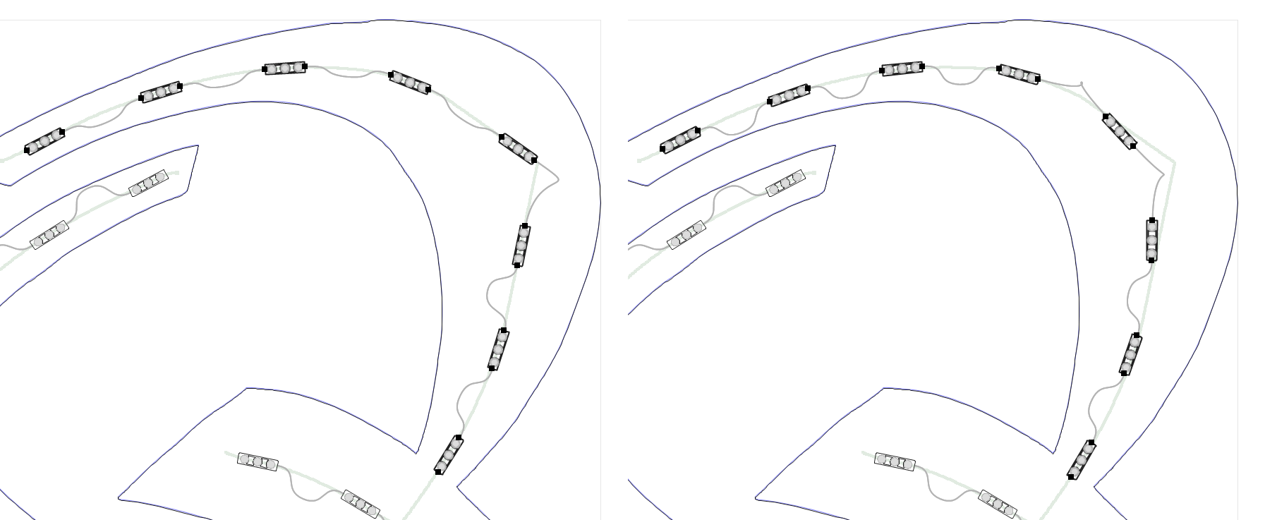
In the run on the left, the mouse position was below the break point when "O" was pressed, and in the run on the right, the mouse position was above the break point. Move Opening - MThis command in PowerFlow will move an opening on a run from one location to another. Like Break Run, the position of the mouse is critical here, so use the shortcut key "M" and position the mouse where you want the new opening to be. The previous opening will be closed. 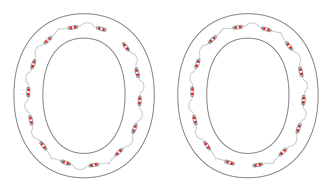
In this example, we want the opening to be at the bottom so that we can more easily wire to our power supply. Convert To Line - [The "[" key (open bracket) will convert the selected modules to a straight line. This is useful when the modules are almost straight, and/or should be straight. Convert to Line will take the positions of the end modules and draw a straight line between them. This line may deviate from any underlying guide path.
In this example, we took the selection and made it into a straight line. And for good measure, we also evenly respaced the modules using the "E" shortcut key. Shift MenuThe Shift Menu provides options for adjusting runs or selections in or out from the return, as well as sliding modules forwards or backwards along the guide path, or to maximum spacing. Shift Inward - Ctrl+<This command will shift the modules inward to the center of the stroke, or away from the return. What's unique about this feature, as opposed to just making a selection of modules and moving it, is that each module is moved independently, perpendicular to the stroke. 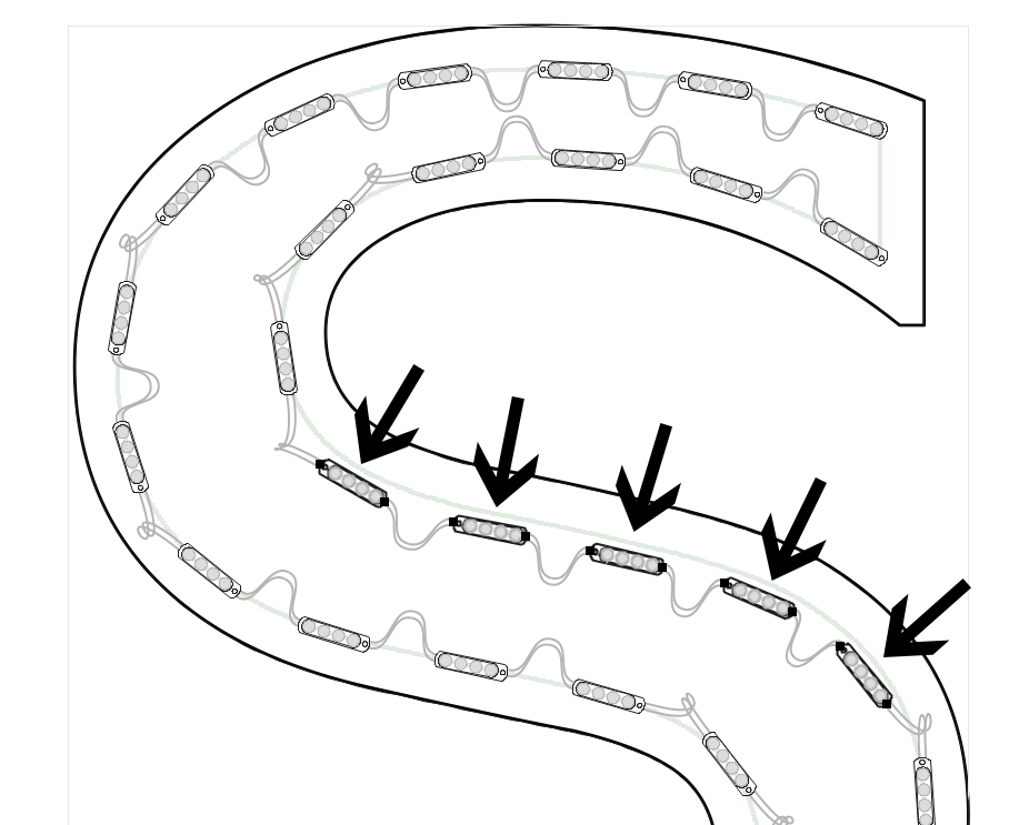
Here there is a subtle stroke width change in this letter, and we want to move the five selected modules in from the return slightly. You can use this in combination with Rotate (Ctrl+X or Ctrl+C) when you want to even out the spacing where a stroke widens. First use Shift Inward and then Rotate to correctly populate a stroke that's somewhere between a single and double row stroke. Shift Outward - Ctrl+>This command will shift the selected modules or run out towards the return, or in the opposite direction from the Shift Inward command. 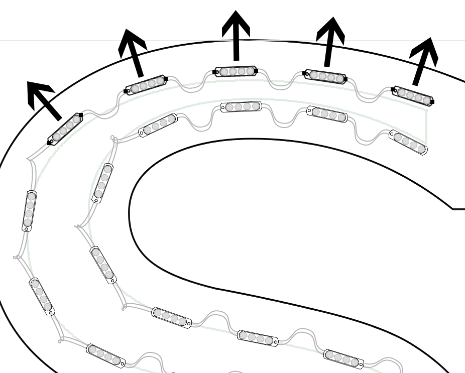
Slide Backward - <This command will slide the selected modules backwards along the path. Slide Forward - >This command will slide the selected modules forwards along the path. Slide to Max Spacing - -This command will adjust the spacing for the selected module so that it is spaced the maximum amount. Reconnect RunsThe Reconnect Runs function will connect runs from a parallel layout in one operation, as opposed to having to connect each line manually. In this example, we start with the population on the left, and then connect them in the graphic on the right. Note that sometimes with parallel runs, the Row Spacing is larger than the Module Spacing, leading to unreachable red wires connecting the runs. Be sure to select all the modules and runs that you want to connect. If you want to connect all modules in the layout, then you can use SHIFT+A to select all. 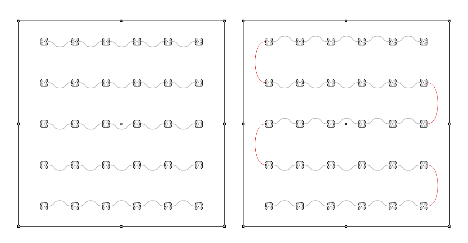
Center in Stroke - Shift+CSometimes a run doesnt populate cleanly in the center of a stroke, but you can use the Center in Stroke function to help. Press "Shift+C" to center the selected modules or the current run within the stroke of the letter.
Here in this example, there is a kink in the center path for this stroke. Just select the modules and use this command. Also remember that holding the ALT key while in PowerFlow will place the cursor in the center of the stroke if you want to manually drag the path or place modules individually. Center in Stroke w/Cleaning - Ctrl+Shift+CPress Ctrl+Shift+C to center the selected modules or the current run within the stroke of the letter, and remove any modules that are too close to the resulting centered modules. This is useful when two strokes are too close together and you want a single stroke. This graphic shows a common case where a stroke is barely thick enough for a second run in a short section. In this case we want to keep just the single run and delete the two modules that make up the second run. Perhaps a better layout option is use Rotation to put in an extra module in the same run. Mouse MenuMove Module: Click+DragTo move a module, click on the module and drag. When the module is near an inline guide, the module's position and rotation will be determined by the inline. If you hold down Alt, you can force the module into the center of the stroke. If you hold down Ctrl, the module can be moved anywhere. Freely Move Module: Select+Ctrl+DragTo freely move a module or selection, click and drag while holding down Ctrl. This is often used in combination with Ctrl+X and Ctrl+C to position and rotate the module precisely. Using Ctrl will also auto rotate the module based on the path created by the mouse movements. To reset this path, release Ctrl and press Ctrl again. Free Drag: Ctrl+Click+DragTo create a new run in a free form manner, click and drag while holding down Ctrl. The path of the mouse will be used to create a smooth path for the modules. This is useful with cursive letters that intersect and there is no well defined stroke to use. Drag to Copy: Ctrol+Drag SelectionTo copy a selection to other location in the same letter, make a selection and then hold down Ctrl as you click and drag. Stop the drag where you want the new modules to be placed. If you want to copy modules to a different letter, you need to use a different approach - select all modules with Shift+A, click on the other letter and then press Shift+V. Create Selection: Shift+ClickTo create a selection, simply hold down Shift while clicking another module in the same run. As you move the mouse while holding down Shift, the modules in the perspective selection will be highlighted. Force Center of Stroke: Alt+DragTo drag a path in the center of the stroke, hold the Alt key while you drag the mouse. Or to manually position and add a module one at a time, hold the Alt key to find the center of the stroke, and then click the mouse to add a single module. Nudge - ArrowsThe arrow keys will move the current module or selection by a small amount either up, down, left, or right. Nudge Faster - Shift+ArrowsUsing the arrows with Shift will nudge faster than the regular arrows. Delete Current Run - Ctrl+DCtrl+D deletes the current run of modules. You can undo this. Delete Module(s) - DThe "D" key deletes a single module or all the modules in the current selection. Delete Module(s) and Break - DelThe Del or Delete key deletes a single module or all the modules in the current selection, and breaks the run into two runs. Delete All Modules in Current Letter - Ctrl+DelCtrl+Del removes all modules from the current letter. You can undo this. Delete Modules in All LettersPressing Shift+Ctrl+Delete while in PowerFlow will delete modules from all letters or objects in the layout. Remove Overlapping Modules - Ctrl+Shift+RCtrl+Shift+R removes all overlapping modules automatically. This is normally performed with the Populate commands, but you can use this separately when needed. PowerFlow Measure Mode - Ctrl+TabWhen you are in the PowerFlow tool, press Ctrl+Tab to enter a special mode where you can easily measure the distance between any two points. Just click and drag the measurement, which shows up as a green line. Pressing Ctrl+Tab again will exit this mode. 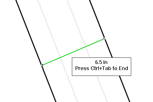
Think of this as the Measure tool, but within PowerFlow. There are various ways to use this tool, the most common being to measure the stroke width at a certain point in a letter, or the distance between two modules. Ensure Reachability - Alt+Shift+RThis will automatically insert modules into the selection until all modules can reach adjacent modules. If you have a layout with some unwanted red wires, this is one option to resolve this issue. The resulting layout will be Respaced as well. Change All ModulesThis is a powerful tool that enables you to change all the modules of a Group, or the entire layout, to another module in one step. First select the populated objects that you want to change with the Layout Tool. If you do not select anything in the layout, then it will change all the objects/modules. Select Change All Modules from the Modify Menu and it will bring up this dialog box. 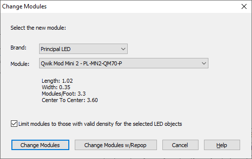
In the dialog box, select the new module, and optionally, the new brand. Note that some basic module information appears here to help you determine if this is the right module. Additionally, the density guidelines of the new module will be used, meaning that the layout may change if the density guidelines of the new module are different from those of the old module. If the new module is in the same Series but just a different color or white color temperature, then assuming that the density guidelines are the same, it will just make a clean one-for-one module switch with the same layout. There is a new option called "Limit modules to those with valid density for the selected LED objects." This means that when this option is checked, only modules with consistent density guidelines, such as the same Can Depth value, will appear as options. Without this option being checked, all modules will appear and you can select any module for the change. If the depth of the sign is such that the density guidelines of the new module do not support that depth, then a warning will appear giving the details and canceling the change. For example, if you have a 3" deep small letter set using Principal Qwik Mod 1 and you try to change to Principal Street Fighter Heavyweight, you'll get the following message: 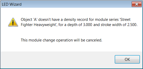
This capability is helpful if you want to present two or more layout options to your customer, both within the same brand or across brands. Previous Next |
 This is a great option in cases where you want to use module rotation on a single run, instead of adding a second run.