The PS Menu contains options for loading power supplies into your layout.
Most of these options are also available, with more automation, in the PowerFlow Tab in the drop down menu to the left of the Load button. Additional options are available in the PS Tab.
Power Supply Edit Mode
This command enters the Power Supply Edit Mode, which makes setting up power supplies a little easier for large cabinets and letters. You can also press the PS Mode button in the property bar for the PowerFlow tool.
Add Selection Rectangle Modules to Power Supply - B
When selecting a rectangular set of modules in Power Supply Edit mode, this command will add those modules to the selected power supply.
Connect Run to Power Supply - C or Shift+Click PS
Press C or Shift+Click on a power supply to add the current run to the power supply. The power supply statistics will be updated.
Remove Run from Power Supply - X or Ctrl+Click PS
To remove a run from a power supply, press X or Ctrl+Click on the power supply itself. The power supply statistics will be updated.
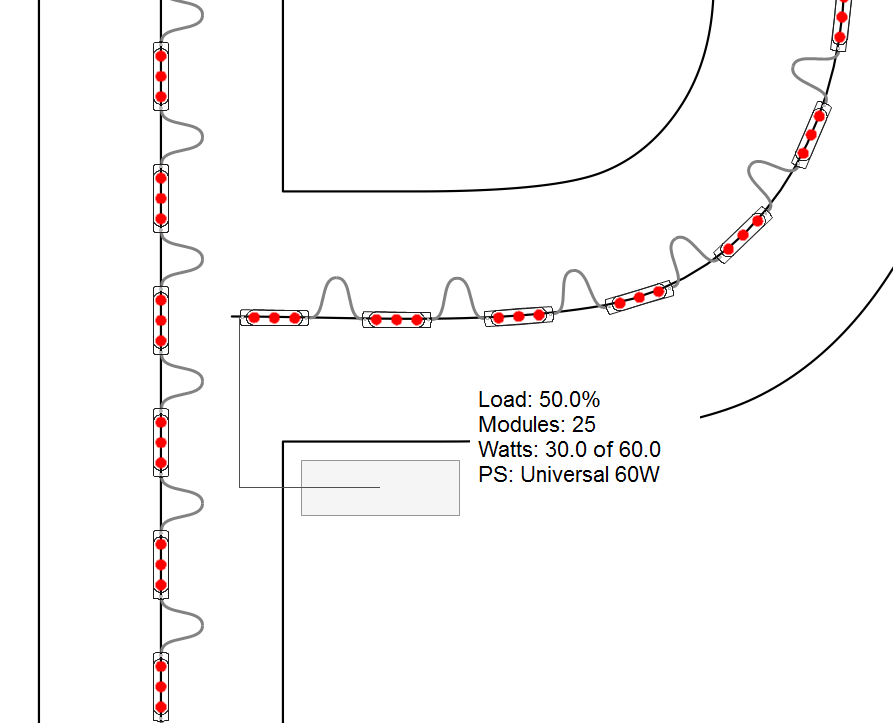
Add New Power Supply - Shift+P
To add a new power supply to the layout, press Shift+P or the + button in the PowerFlow tab. When using Shift+P, the currently selected power supply in the PowerFlow tab is the one added.
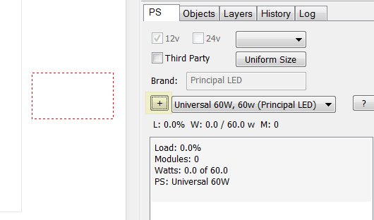
After you click on the + button, drag the power supply into the layout, and click where you want to place it. Here in the image, the red dotted rectangle is the position of the power supply.
Remove Power Supply - Ctrl+Shift+P
When using PowerFlow, to remove the current power supply (highlighted with a red border), select this menu command or press Ctrl+Shift+P.
Add One Power Supply per Letter
This command associates a single power supply with each letter. You select a group of letters to limit this to those letters, otherwise all LED objects are processed. If a group of letters was selected when starting PowerFlow, that group is used. This command is designed for large jobs where any particular letter will not overload the power supply.
Important note: This command can create overloaded power supplies when a letter has too many modules for the selected power supply. If you're not sure which power supply to use, and/or if the layout has a lot of variation, then use [[Add_One_Power_Supply_per_Letter_with_Auto_PS]] instead, which will automatically select the best power supply for each letter.
Add One Power Supply per Letter (Auto Select PS)
This command associates a single power supply with each letter. You select a group of letters to limit this to those letters, otherwise all LED objects are processed. If a group of letters was selected when starting PowerFlow, that group is used.
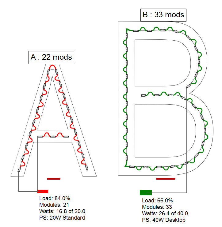
The "Auto Select PS" part of this feature means that it also automatically selects the appropriate power supply for each letter. Or to put it another way, the power supply is not limited to just the one selected.
In this example, these two letters were a Group, and with this feature, the first letter gets a 20W power supply, and the second letter gets a 40W power supply.
Add One Power Supply for All Letters
This command creates a single power supply for the selected letters, or if there is no selection, all the LED objects in the layout. If a group of letters was selected when starting PowerFlow, that group is used. Use this for a smaller letter set or job.
You will have to pre-select the power supply that you want to use from the PS list. To have the system automatically choose the power supply for you, see the next section [[Add_One_Power_Supply_for_All_Letters_with_Auto_PS]].
Add One Power Supply for All Letters (Auto Select PS)
This command creates a single power supply for the selected letters, or if there is no selection, all the LED objects in the layout. If a group of letters was selected when starting PowerFlow, that group is used.
The "Auto Select PS" part of this feature means that the software will choose the best power supply for the job. Using the basic Add One Power Supply for All Letters, you have to select the power supply that you want to use.
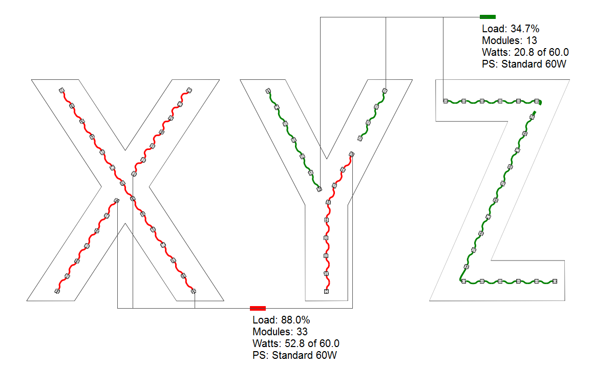
Add Optimal Power Supplies by Letter
This command creates power supplies where the number of power supplies are minimized, assigning the same power supply to multiple letters where possible.
The level of granularity for this feature is the letter, meaning that a letter will not be split between two power supplies.
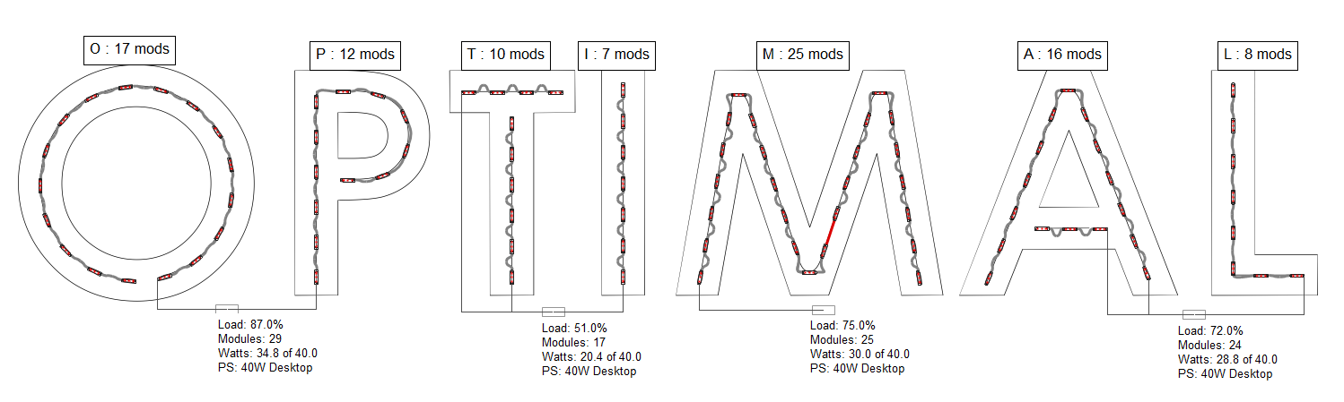
In this example we have four power supplies across seven letters. The "T" and "I" are together on one power supply with a load of only 51%, but the "M" would not also fit, so it gets its own power supply.
Add Optimal Power Supplies by Run
This command creates power supplies where the number of power supplies are minimized, assigning the same power supply to multiple runs where possible.
The level of granularity for this power supply loading option is the run. A run is defined as modules that are connected by wires. Using this option, you can have a letter that is split between two or more power supplies.
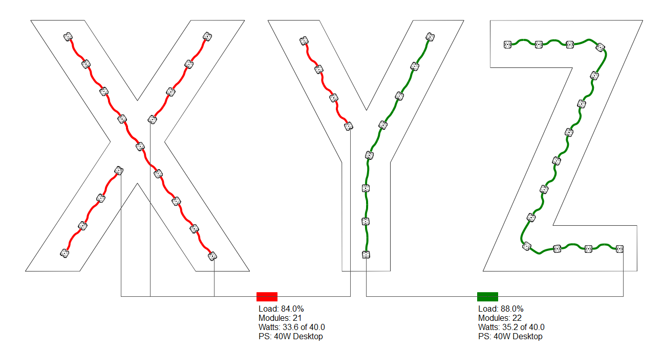
In this example, the Y is split between two 40W power supplies. The use of colored power supplies help see how this is loaded.
Add Optimal Power Supplies by Modules (breaks runs)
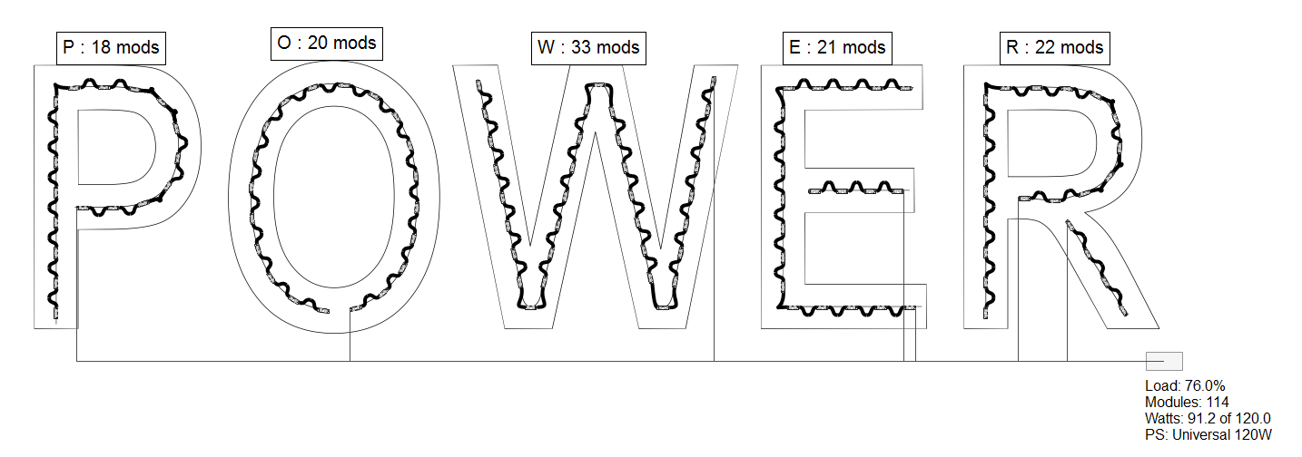
This command creates power supplies that are highly optimized by breaking runs to create the maximum load per power supply and therefore the fewest number of power supplies possible.
The level of granularity of this power supply loading option is down to the individual module. This means that each power supply will be loaded to its margin, or to 100% if there is no margin.
In this example, the power supply has a 12% margin, so the first power supply loads to 88%, then breaks the run and adds a second power supply.
Connect Current Letter to Power Supply - Alt+Click Power Supply
To easily connect all of the runs in the current letter to a power supply, select this command when a power supply is selected (red outline), or Alt+Click on the power supply itself.
Remove Current Letter from Power Supply - Ctrl+Shift+Click Power Supply
To remove all of the runs in the current letter from a power supply, select this command when a power supply is selected (red outline), or use Ctrl+Shift+Click on the power supply itself.
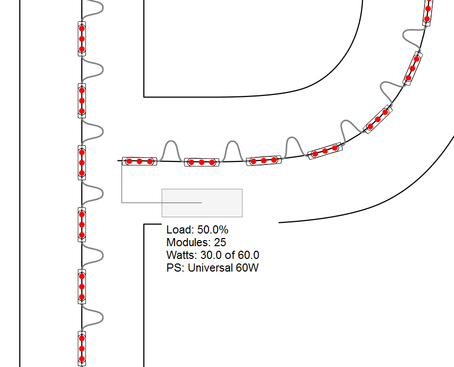
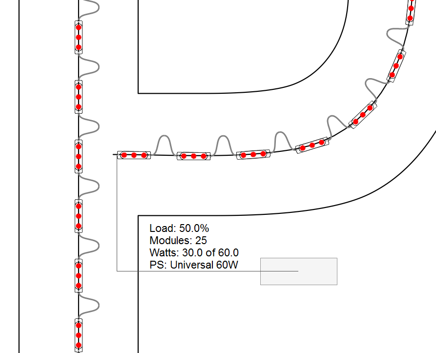
Drawing Left
This command will place the power supply drawing to the left of the power supply stats box.
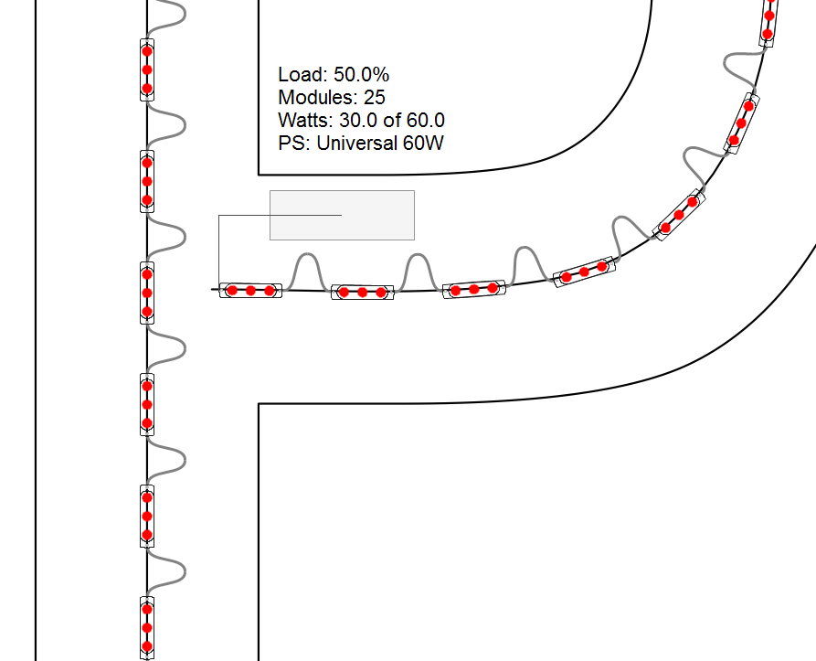
Drawing Above
This command will place the power supply drawing above the power supply stats box.
Drawing Right
This command will place the power supply drawing to the right of the power supply stats box.
Drawing Below
This command will place the power supply drawing below the power supply stats box.
Next Drawing Position
This command will cycle through the four drawing positions for a power supply drawing: left, top, right, bottom.
The shortcut key is Alt+SHift+F11.
Hide Power Supplies
This function will hide power supplies from view, as a way to make a large, complex layout easier to view and manage.
Arrange Power Supplies in a Grid
On large layouts with many power supplies, this function will enable you to arrange your power supplies in a clean grid pattern, as opposed to a long single row.